Avago Technologies LSI8751D User Manual
Page 100
Advertising
4-8
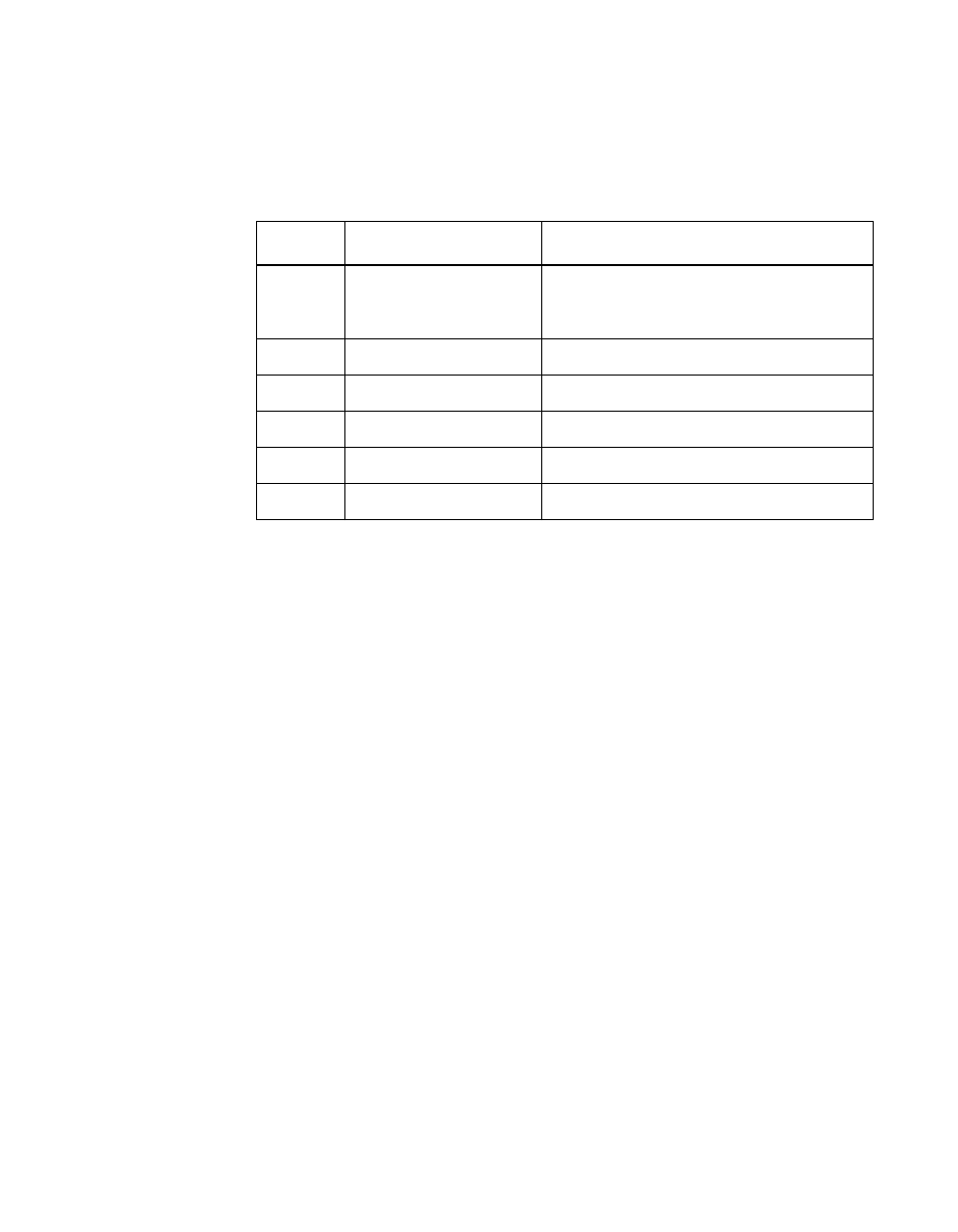
Signal Descriptions
describes the LSI53C875JB and LSI53C875JBE Power and
Ground Signals group.
Table 4.3
LSI53C875JB and LSI53C875JBE Power and Ground
Signals
Name
Pin No.
Description
V
SS
A9, B3, B11, C3, D1,
F4, F5, F6, G5, H4, J3,
K3, K10, M4, N2, N9
Ground to the PCI I/O pins.
V
DD
B10, E8, J7, M10
Power supplies to the Standard I/O pins.
V
DD-I
1
1. These pins can accept a V
DD
source of 3.3 V or 5 V. All other V
DD
pins must
be supplied 5 V.
D2, D5, G1, J5, K1
V
DD
pad for PCI I/O pins.
V
DD
-S
C12, L11
Ground to the SCSI bus I/O pins.
V
SS
-C
L6, C6
Ground to the internal logic core.
V
DD
-C
A5, L5
Power supplies to the internal logic core.
Advertising
This manual is related to the following products: