2 led indications – PLANET MGSD-10080F User Manual
Page 37
User’s Manual of MGSD-10080F
37
■ Digital Input
The digitail input of the Managed Switch can be activated by the external sensor that senses physical changes. These
changes can include intrusion detection or certain physical change in the monitored area. For examples, the external
sensor can be a door switch or an infrared motion detector.
■ Digital Output
The digital output main function is to allow the Managed Switch to trigger external devices, either automatically or by
remote control from a human operator or a software application.
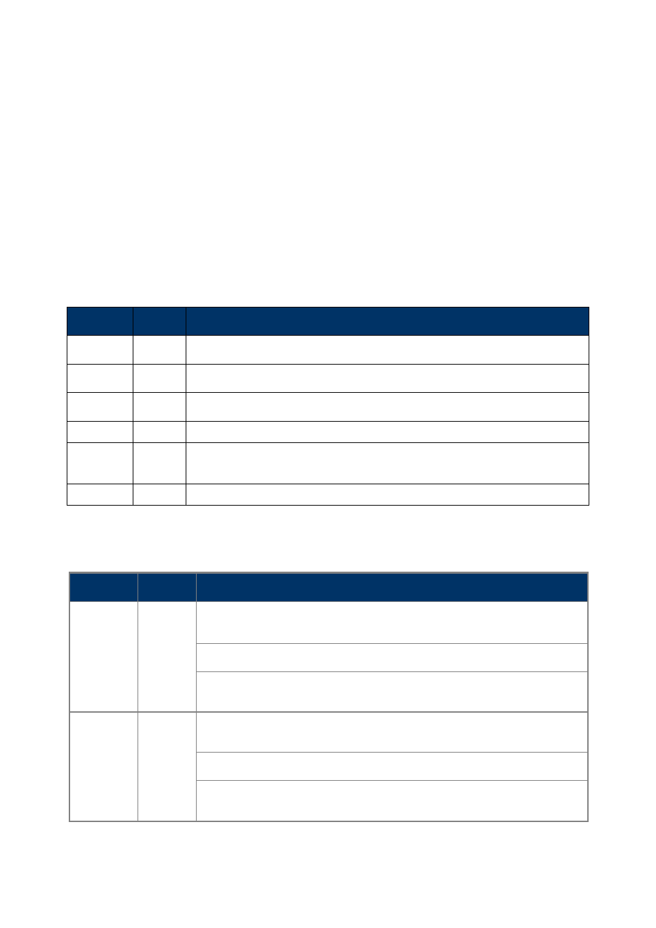
2.1.2 LED Indications
System
LED
Color
Function
PWR
Green
Lights to indicate that the Switch is powered on by AC input.
DC1
Green
Lights to indicate that the Switch is powered on by DC1 input.
DC2
Green
Lights to indicate that the Switch is powered on by DC2 input.
Fault
Green
Lights to indicate that Switch AC/DC or port has failed.
Ring
Green
Lights to indicate that
the ERPS Ring has been created successfully.
R.O.
Green
Lights to indicate that
Switch has been enabled Ring Owner.
Per SFP Interface
LED
Color
Function
1000
LNK/ACT
Green
Lights: To indicate the link through that port is successfully established with speed
1000Mbps.
Blink: To indicate that the switch is actively sending or receiving data over that port.
Off:
If L100 NK/ACT LED light-> indicate that the port is operating at 100Mbps.
If LNK/ACT LED Off -> indicate that the port is link down.
100
LNK/ACT
Orange
Lights: To indicate the link through that port is successfully established with speed
100Mbps.
Blink: To indicate that the switch is actively sending or receiving data over that port.
Off:
If 1000 LNK/ACT LED light-> indicate that the port is operating at 1000Mbps
If 1000 LNK/ACT LED Off -> indicate that the port is link down.
Per 10/100/1000Base-T Interface