ProSoft Technology MVI69-DFNT User Manual
Page 147
MVI69-DFNT ♦ CompactLogix or MicroLogix Platform
Reference
EtherNet/IP Client/Server Communication Module
User Manual
ProSoft Technology, Inc.
Page 147 of 167
May 14, 2014
The following tables define the parameters required for each function.
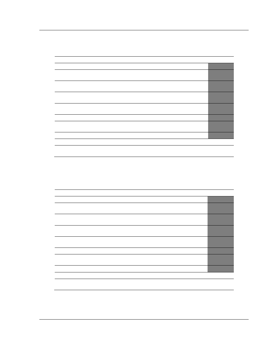
5.8.1 Function Code #1 - Protected Write (Basic Command Set)
Column
Parameter
Description
Parameter
1
Enable/Type Word
0=Disabled, 1=Continuous and 2=Conditional.
2
Virtual Database Address
This parameter defines the database address of the first
data point to be associated with the command.
3
Poll Interval
Minimum time in tenths of a second to wait before polling
with this command.
4
Count
Number of data word values to be considered by the
function.
5
Swap Type Code
Swap type code for command: 0=None, 1=Swap words,
2=Swap words & bytes and 3=swap bytes in each word.
6
Node Address
Address of unit to reach on the data highway.
7
Slot Number
Processor slot number in Control/CompactLogix rack.
Use -1 for PLC5 & SLC processors.
8
Function Code = 1
Protected Write Function
9
Word Address
Word address where to start the write operation.
P1
10 to 12
Not Used
These fields are not used by the command. Values
entered in these columns will be ignored.
P2 to P4
This function writes one or more words of data into a limited area of the slave
device. This function should work on the following devices: 1774-PLC, PLC-2,
PLC-3, PLC-5 and PLC-5/250.
5.8.2 Function Code #2 - Unprotected Read (Basic Command Set)
Column
Parameter
Description
Parameter
1
Enable/Type Word
0=Disabled and 1=Continuous.
2
Virtual Database Address
This parameter defines the database address of the first
data point to be associated with the command.
3
Poll Interval
Minimum time in tenths of a second to wait before
polling with this command.
4
Count
Number of data word values to be considered by the
function.
5
Swap Type Code
Swap type code for command: 0=None, 1=Swap words,
2=Swap words & bytes and 3=swap bytes in each word.
6
Node Address
Address of unit to reach on the data highway.
7
Slot Number
Processor slot number in Control/CompactLogix rack.
Use -1 for PLC5 & SLC processors.
8
Function Code = 2
Unprotected Read Function
9
Word Address
Word address where to start the read operation.
P1
10 to 12
Not Used
These fields are not used by the command. Values
entered in these columns will be ignored.
P2 to P4
This function reads one or more words of data from the PLC memory. This
function should work on the following devices: 1774-PLC, PLC-2, PLC-3, PLC-5,
SLC 500, SLC 5/03, SLC 5/04 and MicroLogix 1000.