ProSoft Technology MVI69-DFNT User Manual
Page 148
Reference
MVI69-DFNT ♦ CompactLogix or MicroLogix Platform
User Manual
EtherNet/IP Client/Server Communication Module
Page 148 of 167
ProSoft Technology, Inc.
May 14, 2014
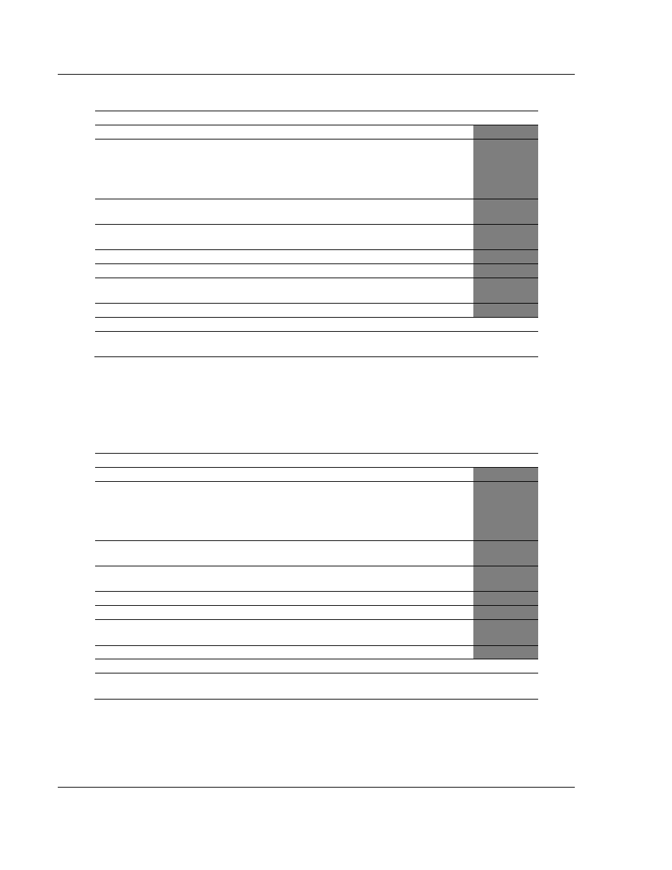
5.8.3 Function Code #3 - Protected Bit Write (Basic Command Set)
Column
Parameter
Description
Parameter
1
Enable/Type Word
0=Disabled, 1=Continuous and 2=Conditional.
Virtual Database Address
This parameter defines the database address for the
data to be associated with the command. The address
defined represents a register address and not a bit
address. This function will update one or more words of
data as defined by the count parameter.
3
Poll Interval
Minimum time in tenths of a second to wait before
polling with this command.
4
Count
Number of data word values to be considered by the
function.
5
Swap Type Code
Swap type code for command: Always zero (0).
6
Node Address
Address of unit to reach on the data highway.
7
Slot Number
Processor slot number in Control/CompactLogix rack.
Use -1 for PLC5 & SLC processors.
8
Function Code = 3
Protected Bit Write Function
9
Word Address
Word address where to start the write operation.
P1
10 to 12
Not Used
These fields are not used by the command. Values
entered in these columns will be ignored.
P2 to P4
This function sets or resets individual bits within a limited area of the PLC data
table. This function should work on the following devices: 1774-PLC, PLC-2,
PLC-3, PLC-5 and PLC-5/250.
5.8.4 Function Code #4 - Unprotected Bit Write (Basic Command
Set)
Column
Parameter
Description
Parameter
1
Enable/Type Word
0=Disabled, 1=Continuous and 2=Conditional.
2
Virtual Database Address
This parameter defines the database address for the
data to be associated with the command. The address
defined represents a register address and not a bit
address. This function will update one or more words of
data as defined by the count parameter.
3
Poll Interval
Minimum time in tenths of a second to wait before
polling with this command.
4
Count
Number of data word values to be considered by the
function.
5
Swap Type Code
Swap type code for command: Always zero (0).
6
Node Address
Address of unit to reach on the data highway.
7
Slot Number
Processor slot number in Control/CompactLogix rack.
Use -1 for PLC5 & SLC processors.
8
Function Code = 4
Unprotected Bit Write Function
9
Word Address
Word address where to start the write operation.
P1
10 to 12
Not Used
These fields are not used by the command. Values
entered in these columns will be ignored.
P2 to P4
This function sets or resets individual bits within a limited area of the PLC data
table. This function should work on the following devices: 1774-PLC, PLC-2,
PLC-3 and PLC-5.