ProSoft Technology MVI69-MCM User Manual
Page 116
Reference
MVI69-MCM ♦ CompactLogix or MicroLogix Platform
User Manual
Modbus Communication Module
Page 116 of 167
ProSoft Technology, Inc.
March 22, 2011
5.4.3 Read Block and Write Block Transfer Sequences
The Read Block ID is an index value used to determine the location of where the
data will be placed in the processor controller tag array of module read data. The
number of data words per transfer depends on the configured Block Transfer
Size parameter in the configuration file (possible values are 60, 120, or 240).
The Write Block ID associated with the block requests data from the processor.
Under normal program operation, the module sequentially sends read blocks and
requests write blocks. For example, if the application uses three read and two
write blocks, the sequence will be as follows:
R1W1→R2W2→R3W1→R1W2→R2W1→R3W2→R1W1→
This sequence will continue until interrupted by other write block numbers sent by
the controller or by a command request from a node on the MODBUS network or
operator control through the module’s Configuration/Debug port.
The following example shows a typical backplane communication application.
If the backplane parameters are configured as follows:
Read Register Start:
0
Read Register Count:
480
Write Register Start:
480
Write Register Count:
480
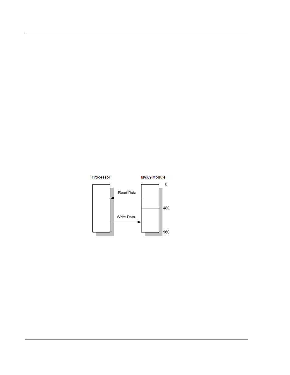
The backplane communication would be configured as follows:
Database address 0 to 479 will be continuously transferred from the module to
the processor. Database address 480 to 959 will continuously be transferred
from the processor to the module.
The Block Transfer Size parameter basically configures how the Read Data and
Write Data areas are broken down into data blocks (60, 120, or 240).