ProSoft Technology MVI69-HART User Manual
Page 87
MVI69-HART ♦ CompactLogix Platform
Reference
HART Multi-drop Master Communication Module
User Manual
ProSoft Technology, Inc.
Page 87 of 169
March 29, 2012
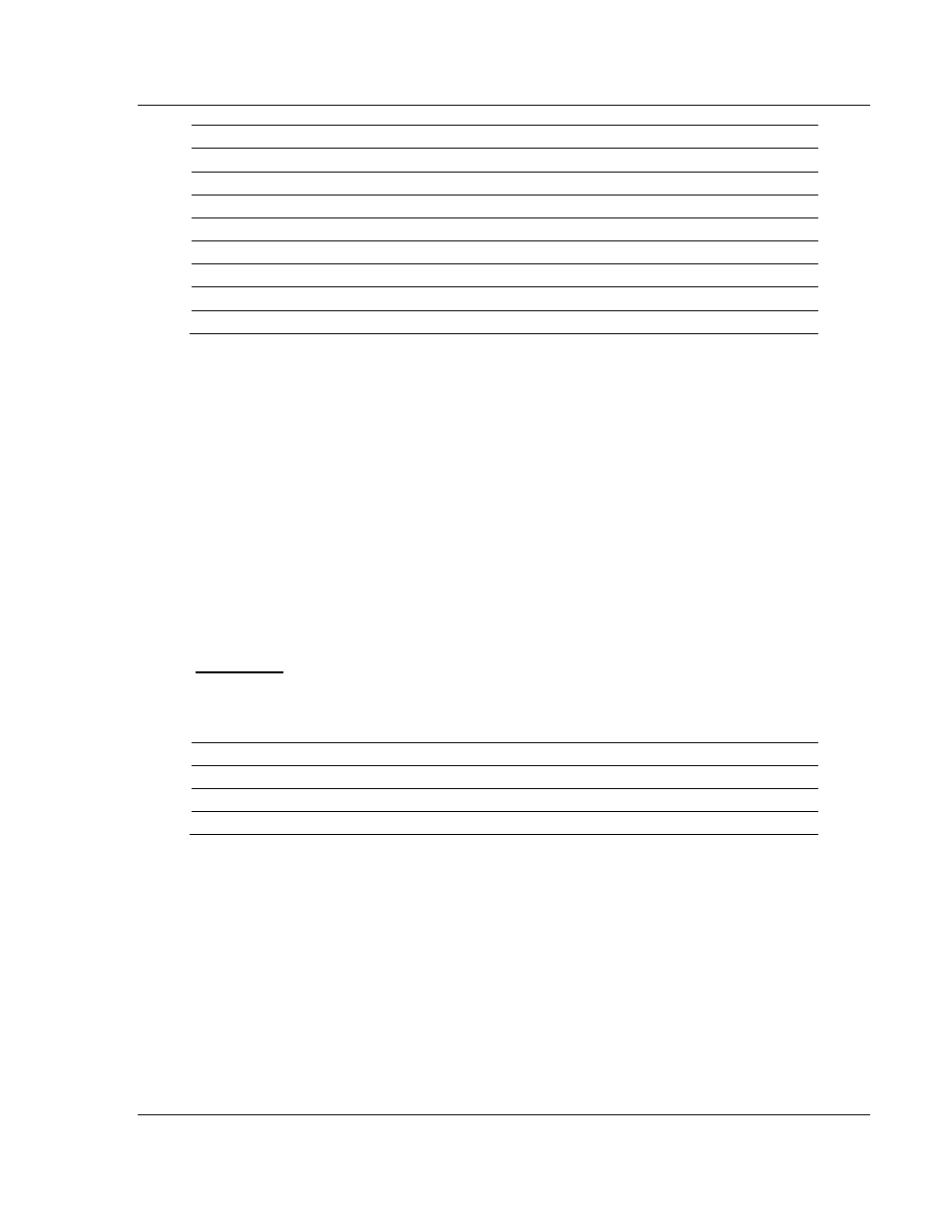
Block Range
Descriptions
-1
Null block (Status Data Only)
0
Null block (Status Data Only)
1 to 20
Read or write data
9902
Command Enable Control Block
9903
Command Disable Control Block
9950
Command List Error data
9998
Warm Boot Request from PLC (Block contains no data)
9999
Cold Boot Request from PLC (Block contains no data)
Blocks -1 and 0 transfer status data from the module to the processor and they
contain no data when transferred from the processor to the module. Blocks 1 to
20 are utilized to transfer data stored or to be stored in the module's database.
These data blocks send data from module to the processor (monitored data
received from the devices on the HART network) and to send data from the
processor to the module (control data to send to the end devices). Block
identification codes 9900 to 9999 are used for special control blocks to control
the module.
5.2.3 Normal Data Transfer
Normal data transfer includes the transferring of data received by, or to be
transmitted to, the master drivers and the status data. These data are transferred
through read (input image) and write (output image) blocks. The structure and
function of each block is discussed in the following topics:
Read Block
These blocks of data transfer information from the module to the CompactLogix
processor. The structure of the input image used to transfer this data is shown
below:
Offset
Description
Length
0
Reserved
1
1
Write Block ID
1
2 to n
Read Data
n
n=60, 120, or 240 depending on the Block Transfer Size parameter (refer to the configuration file).
The Read Block ID is an index value used to determine the location of where the
data will be placed in the CompactLogix processor controller tag array of module
read data. The number of data words per transfer depends on the configured
Block Transfer Size parameter in the configuration file (possible values are 60,
120, or 240).
The Write Block ID associated with the block requests data from the
CompactLogix processor. Under normal program operation, the module
sequentially sends read blocks and requests write blocks. For example, if the
application uses three read and two write blocks, the sequence will be as follows:
R1W1→R2W2→R3W1→R1W2→R2W1→R3W2→R1W1→