Root complex, Chaining dma, Hard ip for pci express – Altera Arria V GZ Avalon-ST User Manual
Page 210
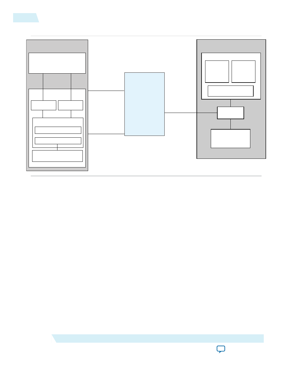
Figure 17-2: Top-Level Chaining DMA Example for Simulation
Root Complex
CPU
Root Port
Memory
Write
Descriptor
Table
Data
Chaining DMA
Endpoint Memory
Avalon-MM
interfaces
Hard IP for
PCI Express
DMA Control/Status Register
DMA Read
Avalon-ST
Configuration
PCI Express
DMA Write
DMA Wr Cntl (0x0-4)
DMA Rd Cntl (0x10-1C)
RC Slave
Read
Descriptor
Table
The block diagram contains the following elements:
• Endpoint DMA write and read requester modules.
• The chaining DMA design example connects to the Avalon-ST interface of the Arria V GZ Hard IP for
PCI Express. The connections consist of the following interfaces:
• The Avalon-ST RX receives TLP header and data information from the Hard IP block
• The Avalon-ST TX transmits TLP header and data information to the Hard IP block
• The Avalon-ST MSI port requests MSI interrupts from the Hard IP block
• The sideband signal bus carries static information such as configuration information
• The descriptor tables of the DMA read and the DMA write are located in the BFM shared memory.
• A RC CPU and associated PCI Express PHY link to the Endpoint design example, using a Root Port
and a north/south bridge.
The example Endpoint design Application Layer accomplishes the following objectives:
• Shows you how to interface to the Arria V GZ Hard IP for PCI Express using the Avalon-ST protocol.
• Provides a chaining DMA channel that initiates memory read and write transactions on the PCI
Express link.
• If the ECRC forwarding functionality is enabled, provides a CRC Compiler IP core to check the ECRC
dword from the Avalon-ST RX path and to generate the ECRC for the Avalon-ST TX path.
17-6
Chaining DMA Design Examples
UG-01127_avst
2014.12.15
Altera Corporation
Testbench and Design Example