Transaction layer configuration space signals – Altera Arria V GZ Avalon-ST User Manual
Page 98
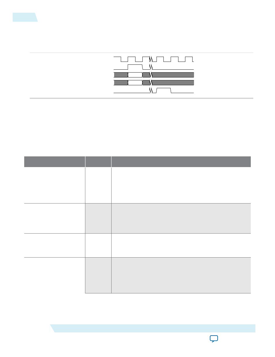
Figure 5-37: LMI Write
Only writeable configuration bits are overwritten by this operation. Read-only bits are not affected. LMI
write operations are not recommended for use during normal operation with the exception of AER
header logging.
pld_clk
lmi_wren
lmi_din[31:0]
lmi_addr[11:0]
lmi_ack
Related Information
Transaction Layer Configuration Space Signals
Table 5-14: Configuration Space Signals
These signals are not available if Configuration Space Bypass mode is enabled.
Signal
Direction
Description
tl_cfg_add[3:0]
0utput
Address of the register that has been updated. This signal is an
index indicating which Configuration Space register information
is being driven onto
tl_cfg_ctl.
The indexing is defined in
Multiplexed Configuration Register Information Available on tl_
cfg_ctl. The index increments on every
pld_clk
cycle.
tl_cfg_ctl[31:0]
0utput
The
tl_cfg_ctl
signal is multiplexed and contains the contents
of the Configuration Space registers. The indexing is defined in
Multiplexed Configuration Register Information Available on tl_
cfg_ctl.
tl_cfg_sts[52:0]
0utput
Configuration status bits. This information updates every
pld_
clk
cycle. The following table provides detailed descriptions of
the status bits.
hpg_ctrler[4:0]
Input
The
hpg_ctrler
signals are only available in Root Port mode and
when the Slot capability register is enabled. Refer to the Slot
register and Slot capability register parameters in Table 6–9 on
page 6–10. For Endpoint variations the
hpg_ctrler
input
should be hardwired to 0s. The bits have the following meanings:
5-46
Transaction Layer Configuration Space Signals
UG-01127_avst
2014.12.15
Altera Corporation
Interfaces and Signal Descriptions