Dma read cycles – Altera Arria V GZ Avalon-ST User Manual
Page 223
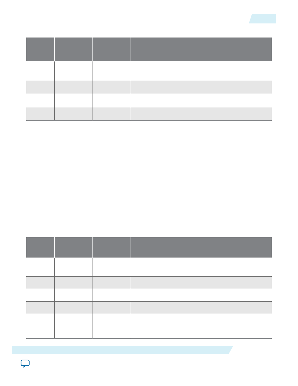
Table 17-14: DMA Control Register Setup for DMA Write
Offset in DMA
Control Register
(BAR2)
Value
Description
DW0
0x0
3
Number of descriptors and control bits as described in
Chaining DMA Control Register Definitions.
DW1
0x4
0
BFM shared memory descriptor table upper address value
DW2
0x8
0x800
BFM shared memory descriptor table lower address value
DW3
0xc
2
Last valid descriptor
After writing the last dword, DW3, of the descriptor header, the DMA write starts the three
subsequent data transfers.
3. Waits for the DMA write completion by polling the BFM share memory location 0x80c, where the
DMA write engine is updating the value of the number of completed descriptor. Calls the procedures
rcmem_poll
and
msi_poll
to determine when the DMA write transfers have completed.
Related Information
Chaining DMA Control and Status Registers
on page 17-10
DMA Read Cycles
The procedure
dma_rd_test
used for DMA read uses the following three steps:
1. Configures the BFM shared memory with a call to the procedure
dma_set_rd_desc_data
which sets
the following three descriptor tables. .
Table 17-15: Read Descriptor 0
Offset in BFM
Shared Memory
Value
Description
DW0
0x910
82
Transfer length in dwords and control bits as described in on
page 18–15
DW1
0x914
3
Endpoint address value
DW2
0x918
0
BFM shared memory data buffer 0 upper address value
DW3
0x91c
0x8DF0
BFM shared memory data buffer 0 lower address value
Data
Buffer 0
0x8DF0
Increment by 1
from 0xAAA0_
0001
Data content in the BFM shared memory from address:
0x89F0
UG-01127_avst
2014.12.15
DMA Read Cycles
17-19
Testbench and Design Example
Altera Corporation