User interface system signals, Using pll resets – Altera HyperTransport MegaCore Function User Manual
Page 55
Chapter 3: Specifications
3–29
HyperTransport MegaCore Function Specification
© November 2009
Altera Corporation
HyperTransport MegaCore Function User Guide
Preliminary
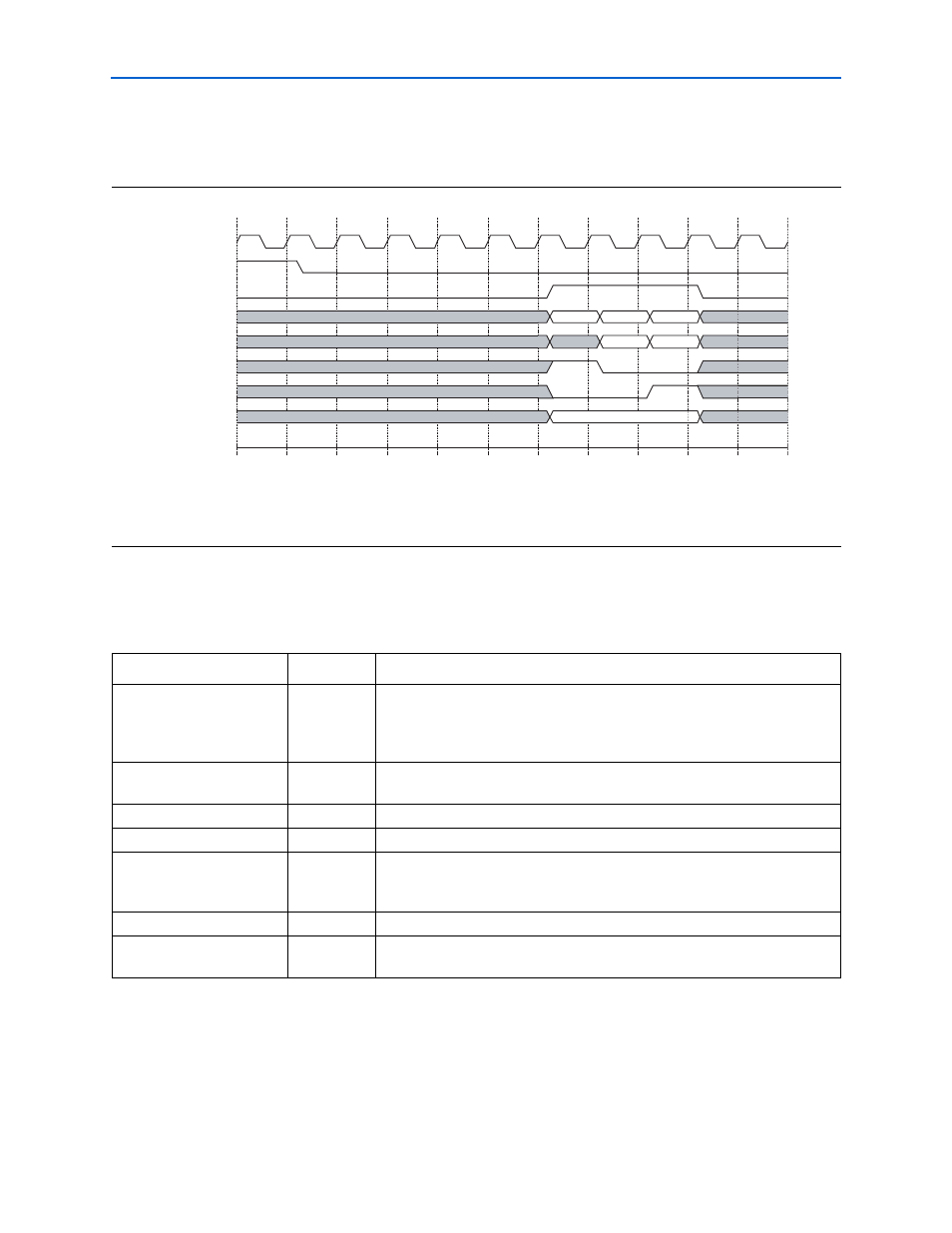
shows the effect of writing to the Tx response buffer with the
TxRDavToSopDelay
parameter set to five.
User Interface System Signals
lists the user interface system signals.
Using PLL Resets
If the input clocks of the fast PLLs used in the HyperTransport MegaCore function
stop and restart, the output phase relationships of the PLL output clocks may not
meet their designed values unless the PLL is reset using these inputs after the clock
has restarted.
Figure 3–19. Tx Response Buffer with the TxRDavToSopDelay Set to 5 Timing Diagram
Notes to
:
(1) In this example,
TxRDatEna_i
is asserted five clock cycles after
Dav_o
is deasserted due to an internal use of the Tx response buffer
(
TxRDatEna_i
was not asserted). This Tx buffer write is not rejected because the
TxRDavToSopDelay
parameter is set to five.
(2)
TxRDat_o[63:32]
is not valid during this time because the command is only a read response.
2
3
4
5
6
7
9
10
RefClk
TxRDav_o
8
1
TxRDatEna_i
TxRDat_i[31:0]
TxRDat_i[63:32]
TxRSop_i
TxREop_i
TxRWrRjct_o
TxRMty_i[2:0]
11
(1)
RdResp
DW0
DW2
DW1
DW3
0b000
(2)
TxRDavToSopDelay = 5
Table 3–9. User Interface System Signals
Signal
Direction
Description
RxLnkClkD4
Output
Clock generated by the Rx PLL. This clock is created based on the transmit
clock of the HT device connected to the MegaCore function’s receiver, and is
four times slower than its source. When using the Shared Rx/Tx/Ref Clock
option, the user interface logic must use this clock.
RxLnkClkD4Locked_o
Output
RxLnkClkD4
lock indicator. This signal is asserted when the Rx PLL is
locked.
RefClkWrmRst
Output
Warm reset signal synchronized to the reference clock input (
RefClk
).
RefClkCldRst
Output
Cold reset signal synchronized to the reference clock input (
RefClk
).
RefClk
Input
Reference clock. This user clock source drives the MegaCore function’s
protocol module. When using the Shared Rx/Tx/Ref Clock option, this input is
not available.
RxPllAreset_i
Input
Resets the HyperTransport Rx PLL used in all clocking modes.
TxPllAreset_i
Input
Resets HyperTransport Tx PLL used in the shared Ref/Tx clocking mode. This
input, which can be tied low, is not used in the other modes.