Altera HyperTransport MegaCore Function User Manual
Page 63
Chapter 3: Specifications
3–37
HyperTransport MegaCore Function Specification
© November 2009
Altera Corporation
HyperTransport MegaCore Function User Guide
Preliminary
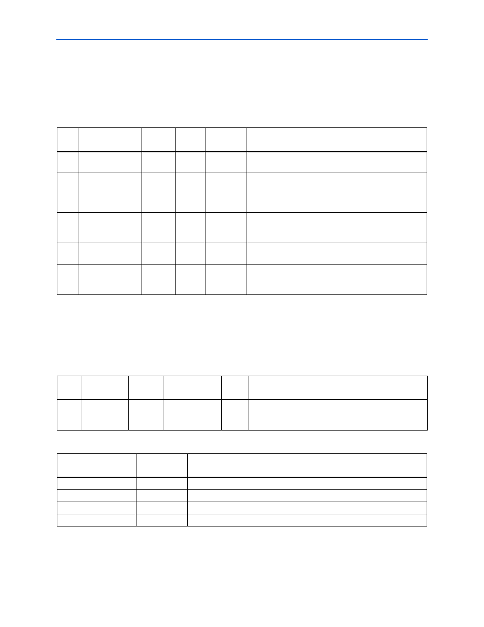
Link Error Registers (Actual Offsets 0x4D, 0x51)
There are two registers of this type, one for each link. In the HyperTransport
MegaCore function, register 0 defines the link connected to the host bridge. For
end-chain applications, only register zero is used.
describes the HT
capability link error registers.
Link Frequency Capability Registers (Actual Offsets 0x4E, 0x52)
Each link frequency capability register is a 16-bit read only register that indicates the
frequency capability of the link. Two registers are defined, one for each link. For
end-chain applications, only register 0 is used.
describe the
link frequency registers.
Table 3–19. HT Capability Link Error 0 Register Offset: Capability Pointer + 0x0D (Actual Offset: 0x4D)
Bits
Name
Register
Type
Default
Reset Used
Description
3:0
Link Frequency
Register
R/W
0
Cold
Intended to control the frequency of the link transmit clock,
but has no effect in the HyperTransport MegaCore function.
4
Protocol Error
R/C
0
Cold
Indicates that a protocol error was detected. The
HyperTransport MegaCore function reports a protocol error
when the
RxCTL_i
signal changes on other than a 4-byte
boundary.
5
Over Flow Error
R/C
0
Cold
Indicates that a packet was received but there was no room
in the Rx packet buffer. Indicates a failure in the flow
control mechanism.
6
End of Chain Error
R/C
0
Cold
Indicates a posted request of response has been given to
this transmitter when it is an end chain.
7
CTL Timeout
R/W
0
Warm
Indicates how long CTL may be low before a device
indicates a protocol error. 0 indicates one millisecond; 1
indicates 1 second.
Table 3–20. HT Capability Link Frequency 0 Capability Register Bits Offset Capability Pointer + 0x0E (Actual Offset: 0x4E)
Bits
Name
Register
Type
Default
Reset
Used
Description
15:0
Supported
Frequencies
R/O
N/A
Indicates the supported frequencies of operation. The
default value is set based on the HT_RX_CLK_PERIOD
Parameter.
Table 3–21. Link Frequency 0 Capability Register Default Value
HT_RX_CLK_PERIOD
Register
Value
Supported Frequencies (MHz)
5000
0x0001
200
3333
0x0003
200, 300
2500
0x0007
200, 300, 400
2000
0x000F
200, 300, 400, 500