Figure 2–1, Ons and, Table 2–1 – Altera Stratix III Development Board User Manual
Page 10: Descr
2–2
Chapter 2: Board Components
Board Overview
Stratix III 3SL150 Development Board
May 2013
Altera Corporation
Reference Manual
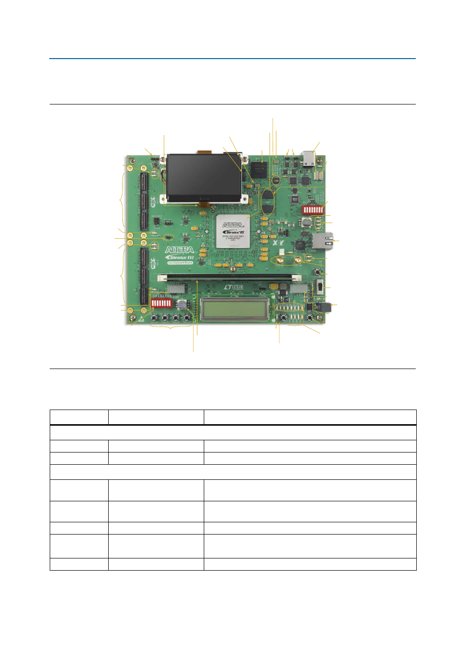
shows the top view of the Stratix III development board.
describes the components and lists their corresponding board references.
Figure 2–1. Top View of the Stratix III Development Board
Stratix III
FPGA (U22)
MAX II
CPLD (U5)
Device Select (J2)
Jumper
24-MHz Crystal (Y2)
6-MHz
Crystal (Y3)
125-MHz MAX II Clock (Y1)
Type B USB
Connector (J5)
MAX II Control
DIP Switch (SW2)
Ethernet PHY
LEDs (D6, D7, D8) &
Duplex LED (D9)
PGM Config Select
Rotary Switch (SW3)
RJ-45 Ethernet
Connector (J14)
Clock In/Out SMAs (J16, J17)
Ethernet PHY TX/RX
Activity LEDs (D14, D15)
Factory Configuration
Push Button (S1)
Power Switch (SW4)
DC Power Jack (J21)
User Push Buttons
(S2 through S5)
Reset Configuration
Push Button (S7)
Configuration
Done LED (D32)
Board-Specific
LEDs (D33-D36)
User LEDs
(D20 through D27)
CPU Reset
Push Button (S6)
Flash Memory Device (U9)
24-MHz Crystal (Y4)
DDR2 SDRAM
(U17, U20)
DDR2 SDRAM
DIMM Connector (J19)
Power Select
Rotary Switch (SW6)
Power LED (D16)
HSMC Port A (J18)
HSMC Port B (J8)
HSMC Port A
Present LED (D17)
Power Display (U27)
User DIP Switch (SW5)
HSMC Port A
TX/RX Activity
LEDs (D11, D12)
HSMC Port B
Present LED (D10)
Speaker Header (J1)
HSMC Port B
TX/RX Activity LEDs
(D2, D3)
User Display (U28)
QDRII+ SRAM (U15)
(Behind the LCD Screen)
JTAG Control DIP Switch (SW1)
MSEL0 to GND
Jumper (J13)
Table 2–1. Stratix III Development Board (Part 1 of 3)
Board Reference
Type
Description
Featured Devices
U22
FPGA
EP3SL150F1152, 1152-pin BGA package.
U5
CPLD
EPM2210GF256, 256-pin device in a BGA package.
Configuration Status and Setup Elements
J2
Device select (DEV_SEL)
jumper
Sets target device for JTAG signals when using an external USB Blaster
or equivalent.
J5
Input
Type B USB connector that allows for connecting a Type A-B USB cable
between a PC and the board.
D32
Configuration done LED
Green LED that illuminates when the FPGA is successfully configured.
D11, D12 (Port A)
D2, D3 (Port B)
Channel activity LEDs
Green LEDs that indicate the RX and TX activity on the HSMC Ports A
or B.
J1
Header
Speaker header.