User-defined dip switches, User-defined dip switches –29 – Altera Stratix III Development Board User Manual
Page 37
Chapter 2: Board Components
2–29
General User Interfaces
May 2013
Altera Corporation
Stratix III 3SL150 Development Board
Reference Manual
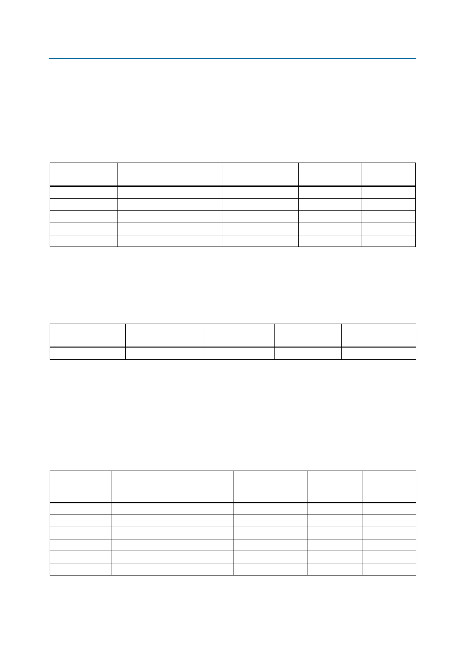
Board reference S6 is the user reset push-button switch, CPU_RESET, which is an input
to both the Stratix III device and MAX II CPLD. The CPU_RESET is intended to be the
master reset signal for the FPGA design loaded into the Stratix III device. Still, the
CPU_RESET
is also a regular I/O pin. The MAX II device uses the DEV_CLR pin as its
reset along with the RESET_CONFIG push-button switch.
lists the schematic signal names and corresponding Stratix III pin
numbers.
lists the push-button switch component reference and manufacturing
information.
User-Defined DIP Switches
Board reference SW5 is an 8-pin DIP switch. The switches in SW5 are user-defined,
and are provided for additional FPGA input control. Each pin can be set to a logic 1 by
pushing it to the open position, and each pin can be set to a logic 0 by pushing it to the
closed position. There is no board-specific function for these switches.
lists the user DIP switch settings, schematic signal name, and
corresponding Stratix III device’s pin number.
Table 2–21. User Push-Button Switch Signal Names and Functions
Board Reference
Description
Schematic
Signal Name
Stratix III Device
Pin Number
Other
Connections
S2
User-defined push-button
USER_PB3
K17
—
S3
User-defined push-button
USER_PB2
A16
—
S4
User-defined push-button
USER_PB1
A17
—
S5
User-defined push-button
USER_PB0
B17
—
S6
User-defined push-button
CPU_RESET
AP5
U5 pin M9
Note to
:
(1) The pull-up resistors for the push-buttons are connected to 2.5 V. The inputs pads on the FPGA can accept an input voltage up to the maximum
input voltage for the device. The logic threshold is determined by the VCCIO of the bank and the selected I/O configuration.
Table 2–22. Push-Button Switch Component Reference and Manufacturing Information
Board Reference
Description
Manufacturer
Manufacturing
Part Number
Manufacturer
Website
S2 through S6
Push-button switch
Panasonic
EVQPAC07K
Table 2–23. User-Defined DIP Switch Pin-Out (SW5) (Part 1 of 2)
Board Reference
Description
Schematic
Signal Name
I/O Standard
Stratix III
Device
Pin Number
SW5 pin1
User-defined DIP switch pin 1
USER_DIPSW0
1.8 V
B19
SW5 pin 2
User-defined DIP switch pin 2
USER_DIPSW1
1.8 V
A19
SW5 pin 3
User-defined DIP switch pin 3
USER_DIPSW2
1.8 V
C18
SW5 pin 4
User-defined DIP switch pin 4
USER_DIPSW3
1.8 V
A20
SW5 pin 5
User-defined DIP switch pin 5
USER_DIPSW4
1.8 V
K19
SW5 pin 6
User-defined DIP switch pin 6
USER_DIPSW5
1.8 V
J19