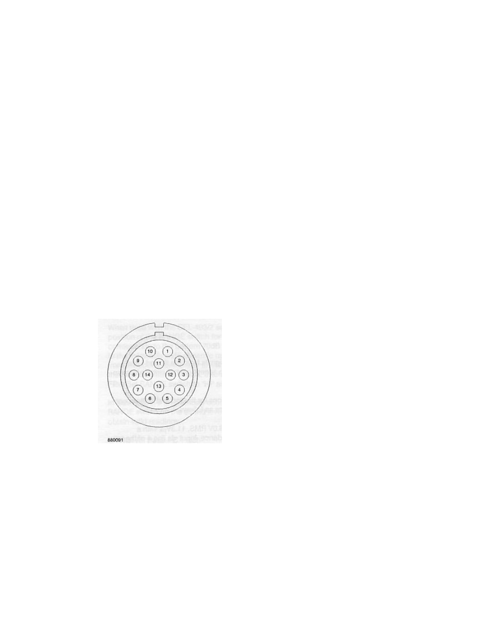
Figure 6 external view of top connector – Casella CEL CEL-296 User Manual
Page 25
are used to recall the stored spectral data, band by band, from either
the full octave or 1/3 octave memories.
3.5 Input Facilities
The CEL-296/3 can accept analog noise signals from the sound
level meter for frequency analysis.
It will also accept control signals from an external device to step the
filters, and digital data from a suitably equipped sound level meter
for display and storage via the CEL low power serial Interface.
Figures 6 and 7 show the line connections for the top and bottom
connectors. Interfacing Is comprehensively described In Chapter 6.
The analog input conditions are as follows.
1. Batt
+
2. Batt
–
3. Not
used
4.
AC to filter from SLM
5. Analog
ground
6.
AC from filter to SLM
7.
UP function of SLM
8. Pause
SLM
9.
Request to send from SLM
10.
Serial data from SLM
11.
Remote reset of SLM
12.
Clear to send to SLM
13.
Log DC out from SLM
14.
Event in progress (CEL-493/2 only)
* Used only with sound level meters equipped with the
CEL low power interface
Figure 6 External view of top connector
CEL Instruments Ltd
CEL-296/3 Operator Handbook
Page 25