Casella CEL CEL-296 User Manual
Page 26
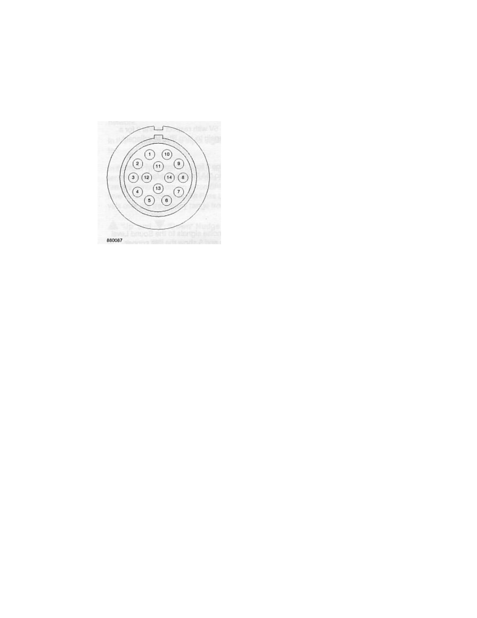
1. Batt
+
2. Batt
–
3.
Filter step up
4.
AC from filter
5. Analog
ground
6.
All pass reset filter
7.
Up function of SLM
8. Pause
SLM
9.
Request to send from SLM
10.
Serial date from SLM
11.
Remote reset of SLM
12.
Clear to.send to SLM
13.
Log. DC out from SLM
14.
Event In progress (CEL-493/2 only)
* Used only with sound level meters equipped with the
CEL low power interface
Figure 7: External view of bottom connector
Conditioned AC signals up to 8.0 V RMS, 11.3 Vpk with a maximum
of 1 kΩ source impedance, input via line 4 of the top connector.
The remote control facilities are as follows.
1. Filter step up: raise line 3 to 1 5 V with respect to line 2 for a
minimum of 25 ms, then open again to step filter to adjacent higher
frequency band.
2. All stop reset: close line 6 to line 2 for a minimum of 25 ms, then
open again to reset scan to "All Stop" band for start of a remote
scan.
3.6 Output Facilities
The CEL-296/3 can deliver filtered analog noise signals to the sound
level meter for level measurement. It will also transmit digital data
from its storage facilities to suitably equipped recorders or data
loggers via the CEL low power serial interface.
Page 26
CEL-296/3 Operator Handbook
CEL Instruments Ltd