2 layout & controls – Casella CEL CEL-310 User Manual
Page 7
When a measurement is downloaded from the Reader to the
Dose Badge Software, the configuration of the Dose Badge is shown.
PLEASE NOTE that the Microphone Response shown as “F”
does not indicate Fast time weighting, but rather Free Field microphone
response.
The Reader controls the Dose Badge via an infrared link with
information sent backwards and forwards in a similar way to a television
remote control.
PLEASE NOTE that the range of communication is very much
shorter than a television remote control.
Each Dose Badge contains a rechargeable battery, where a
single charge of the battery is intended to supply sufficient power for a
measurement lasting up to 16 hours. However, the Dose Badge can run
for much longer when the battery is fully charged.
1.2
Layout & Controls
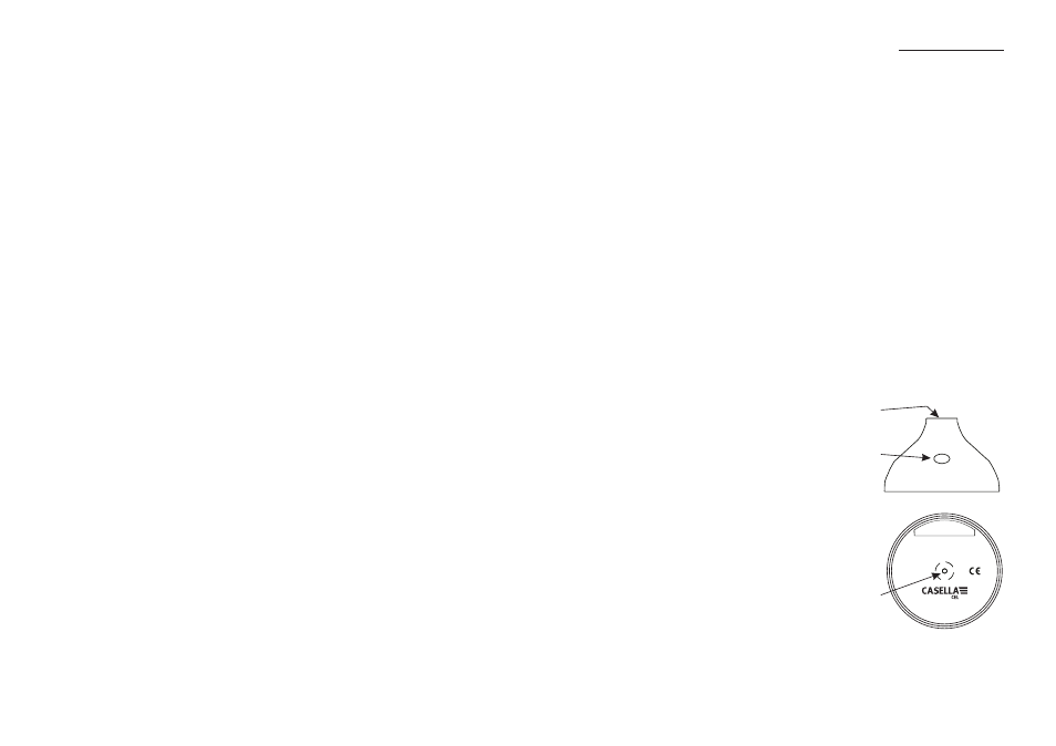
The layout of the Dose Badge is shown in Figure 2.
The microphone is mounted at the top of the case in a shock
mount that reduces the noise generated from movement or handling.
A window allows access for
the infrared control signals from the
Reader Unit. Ensure that this window
is clean and free from dust and dirt.
The charging connection for the
internal battery is at the centre of the
bottom panel. This threaded insert is
also used to attach the Dose Badge.
The Reader Unit, shown in
Figure 3, has an integral acoustic
calibrator that has been specifically
designed to suit the unique shape and
performance of the Dose Badge. The
calibrator cavity is located in the top
panel of the Reader.
Microphone
CEL-310
03002
Charging/
mounting
stud
Infrared
window
0000
www.casellacel.com
Serial
Number
ANSI S1.25-1991 Class: see manual
or IEC 61252: 1993
Figure 2: The Dose Badge
Introduction
CEL-310 Dose Badge Users Handbook - Page 7