Junger Audio MIX4 Small Desktop Mixer User Manual
Page 13
Jünger Audio-Studiotechnik GmbH
page
10
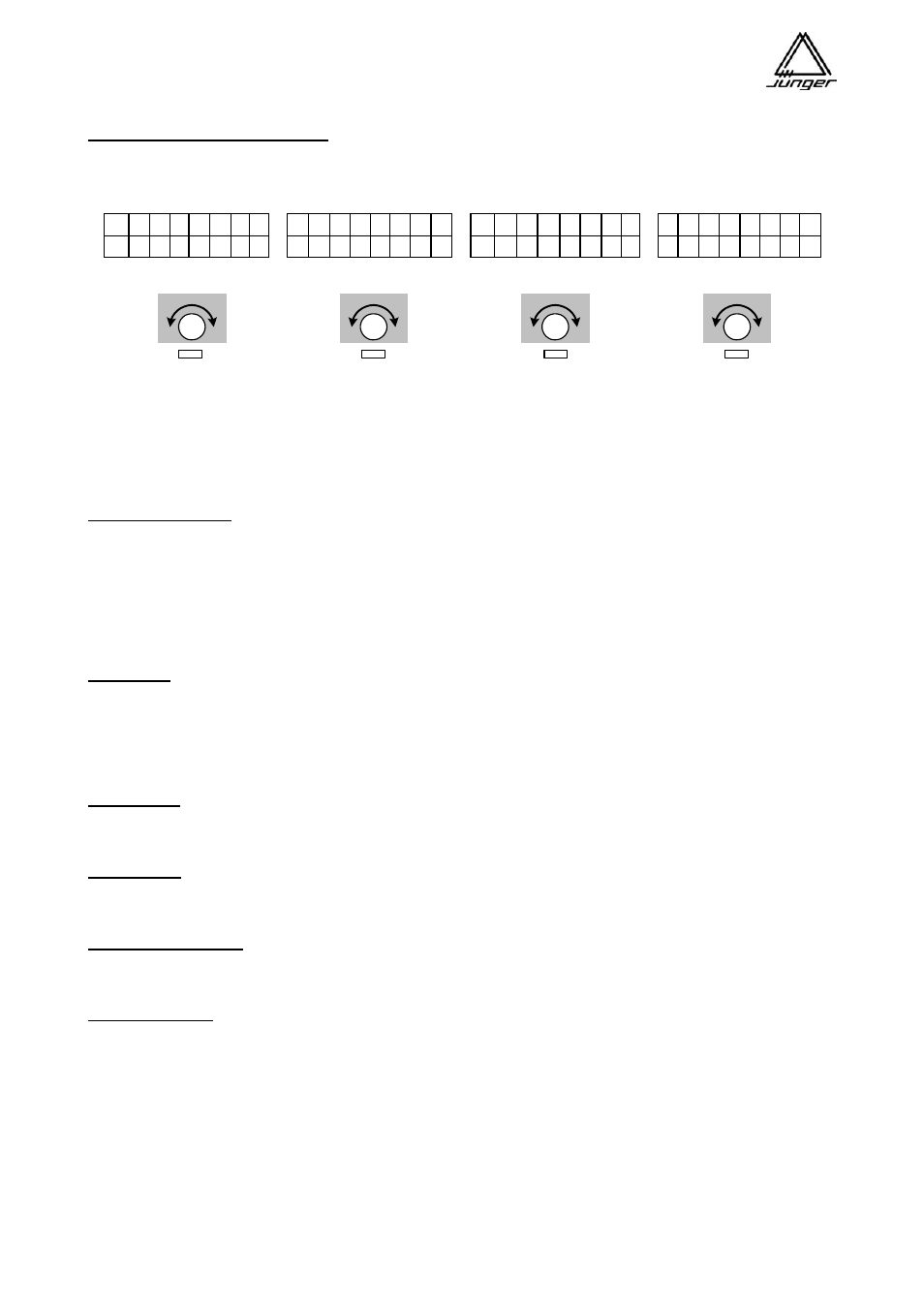
Prefade / Postfade Send Levels :
When one bus or more buses are configured as Prefade mix or Postfade mix and the respective Bus-
Monitor button is pressed then the top display line shows level of each channel to the mix, e. g. <Bus 3>
L C R 1 2 3 4 L C R 1 2 3 4 L C R
1 2 3 4
L C R 1 2 3 4
P
r e
F
a
d
e r M i x B u s 3
o f f - 1 0 , 0 d B o f f + 3 , 0 d B
The Mic 1 is currently not yet assigned to Prefade bus3, and by turning the Channel Rotary Knob A it is
included in the mix with -83 dB and can be modified by further turning the Channel Rotary Knob by up to +10
dB.
Important note! This display is left by pushing another Bus Monitor button.
Button operations :
Buttons which control external devices or perform PFL or DIM can operate in two different modes:
Toggle switch operation
If
one
presses the button once briefly the function will be turned on
If
one
presses the button once briefly again the function will be turned off
Push button operation
If
one
presses and holds the button the function will be turned on
If
one
releases the button the function will be turned off
Shortcuts :
For quick access to the first eight Presets or one of the 8 Snap-Shots there is a shortcut function
implemented. Pressing the <DSP> button first and one of the <USERx> or <BUSx> buttons afterwards
loads the respective Preset into the Channel Strip which has been pre selected by the setup software.
Pressing the <USER> button first and one of the <USERx> or <BUSx> buttons afterwards loads the
respective SnapShot.
N-1 busses :
The MIX4 knows one N-1 bus configuration to operate a telephone interface. This function is called HYBRID
(s. p. 57). All other N-1 configurations must be set manually.
PFL modes :
The MIX4 has exclusive and summing PFL functions that can be turned off and on automatically, depending
on the fader position (s. p. 20).
Test tone generator :
For testing purpose of outgoing lines you can route a 1kHz test tone to the busses of the MIX4 (s. p. 20). The
level of that signal can be set from the desktop remote.
Monitor section :
The 4 busses of the MIX4, sources (MIX4 inputs) assigned to Channel Strips and those not assigned to a
Channel Strip can be monitored via the monitor root (functions called: bus monitoring, PFL and source
monitoring). The monitor line output and two parallel headphone outputs are connected to that root. Both
headphone outputs together and the monitor line output have level controls to set the monitoring loudness.
Two auxiliary outputs (analog and digital both 2CH) may also be connected to the monitor root by use of the
setup software (e.g. to connect an external meter to the MIX4). The LED level and phase display has only
effect for bus monitoring and for PFL. It is not active for source monitoring.