Configuring analog input parameters – Measurement Computing DAQLog User Guide User Manual
Page 19
DAQLog Software User's Guide
Working with Settings Files and Folder Locations
19
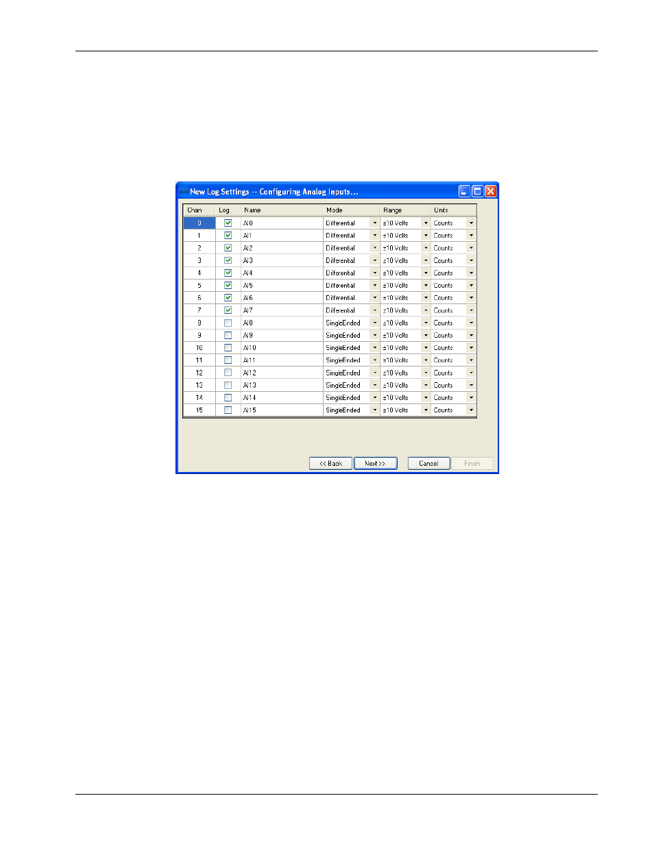
Configuring analog input parameters
The
New Log Settings…Configuring Analog Inputs…
dialog contains a grid of parameters that determine:
the analog input channels to log
the configuration mode of each analog input channel (single-ended or differential)
the voltage range of data to log
the units to use on the logged data
Each column in this grid is explained below.
Chan
: List the number of each analog input channel. You cannot edit the numbers in this column.
Log:
Select the check box of each analog channel whose data you want to log.
Name:
Double-click on a cell in this column if you want change/add to the default name. This name appears in
the column header for the channel's log data when you view the data file in a spreadsheet.
Mode:
Select the mode that the channel is physically wired to use when acquiring data.
Refer to the “Screw terminal pin out” section in the “Specifications” chapter of your LGR-5320 Series device
user’s guide for your device’s differential and single-ended pin out.
Range:
Select the voltage range of the data to log.
If you select ±30 Volts for a channel configured for differential mode, the associated high/low channel is also
set to ±30 Volts.
For example, if analog input channel 0 (
AI0
) is set to Differential in the
Mode
column and to ±30 Volts in the
Range
column,
AI8
is also set to ±30 Volts.
Units:
Select the units—Counts, Volts, or mV—to use when converting log data.
Set the analog input parameters on this dialog and click
Next>>
to open the
New Log Settings…Configuring
Counter Inputs…
dialog..