Setting reset, index, and modulo parameters – Measurement Computing DAQLog User Guide User Manual
Page 21
DAQLog Software User's Guide
Working with Settings Files and Folder Locations
21
o
Counter
: Use this mode for high-speed pulse and general counter operations. You can use the Index input
to clear, gate, latch, or decrement the counter.
o
Up/Down Counter
: In this mode, phase A is the pulse source and phase B is the direction. The counter
changes direction depending on the state of phase B. The Phase B Edge setting determines whether a high
or low signal at phase B causes the counter to count up.
o
Encoder
: Measure the system position (counts), velocity (counts per second), and direction of rotation.
This mode supports encoders with X1, X2, and X4 count modes.
o
Period
: Measure the period of a signal at a counter channel's phase A input. You can measure x1, x10,
x100 or x1000 periods.
o
PulseWidth
: Measure either the time from the rising edge to the falling edge, or the time from the falling
edge to the rising edge on a counter channel's phase A input.
o
Timing
: Measure the time between the rising or falling edge on the phase A input and the rising or falling
edge of the Index channel. The edges used are determined by the Phase A Edge and Index Edge options
settings.
Refer to the “Screw terminal pin out” section in the “Specifications” chapter of your LGR-5320 Series device
user’s guide for your device’s counter signal pin out.
Option:
Depending on the
Mode
selected, you can set these counter options:
Counter
and
Up/Down Counter
mode options
o
Totalize
The counter counts rising edges or falling edges.
o
Clear On Read
: The counter is cleared after each synchronous read. The counter value is latched and
returned before it clears.
Encoder
mode options
o
1X
: Counts rising or falling edges on phase A, depending on the phase A Edge setting (
Encoder
mode
only).
o
2X
: Counts rising edges and falling edges on phase A.
o
4X
: Counts rising edges and falling edges on phase A and phase B.
Period
mode options
o
1 Period
: The measurement latches after one complete period is observed
o
10 Period
:The measurement latches after 10 complete periods are observed .
o
100 Period
:The measurement latches after 100 complete periods are observed.
o
1000 Period
:The measurement latches after 1000 complete periods are observed.
Tick Size
: For
Period
,
PulseWidth
and
Timing
modes, you can set the counter tick size measurements. The
system clock of the field programmable gate array (FPGA) is 20 ns.
o
20 ns
: Sets the counter channel's tick size (timebase) to 20 nanoseconds.
o
200 ns
: Sets the counter channel's tick size to 200 ns.
o
2 µs
:Sets the counter channel's tick size to 2 microseconds
o
20 µs
: Sets the counter channel's tick size to 20 µs
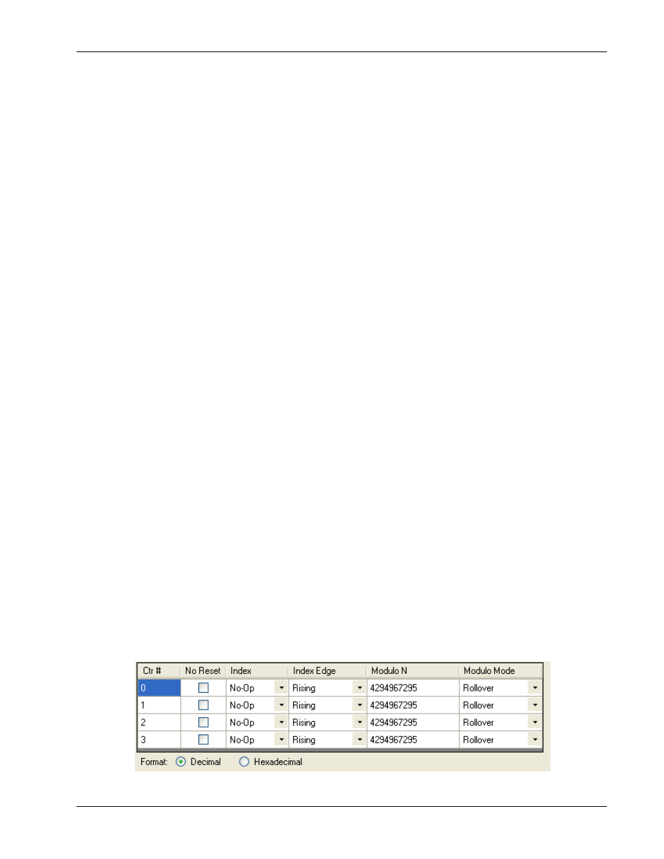
Setting reset, index, and modulo parameters
The parameters in the bottom grid of the
Counter Settings
area of the dialog are explained below.