Electrical system, 1 circuit diagram and control box, Circuit diagram and control box – MovinCool Office Pro W20 Service Manual User Manual
Page 27
Operation Section
27
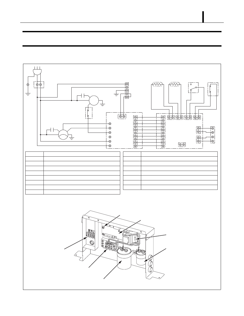
6. ELECTRICAL SYSTEM
6.1 Circuit Diagram and Control Box
ILL00137-00
Relay Board Fuse
Relay Board
Fan Motor Capacitor
Compressor Capacitor
Terminal Block
Dip Switch
Terminal Block
(Signal Connections)
AC 115 V 1
φ
60 Hz
AP
G
G
G
HI
LO
MC
CN
RTH
THS
DS
HPRS
CB
TB2
L-
J106
J108
J105
J101 J102 J103 J104
J201
L+
E-
E+
3
2
1
Jumper
Line
MF
IOLF
1 2
CF
CC
1 2
G
G
T R
J9
J8
RB
J6
J5
J4
J3
J2
J1
A
P
T B 1
T B 2
C
B
R
B
M
F
M
C
C
F
C
C
Attachment Plug
Terminal Block
Terminal Block
Control Board
Relay Board
Fan Motor
Compressor Motor
Capacitor for Fan Motor
Capacitor for Compressor
I O L F
O L C
D
S
T H S
R T H
H P R S
G
C
N
Inner Overload Relay of Fan Motor
Inner Overload Relay of Compressor
Full Drain Warning Switch
Freeze Protection Thermistor
Room Thermistor
High Pressure Switch
Grounding
Connector for Option Drain Pump
TB1
1
2
OLC