Pacific Research Solutions RI-1 User Manual
Page 24
Pacific Research Solutions
RI-1 and PE-1 User Manual
Page 18
ADJUSTING THE REPEATER TRANSMITTER MODULATION
After hooking up the repeater transmitter audio and the repeater PTT keying circuit per Section 4, you will need to adjust the
repeat TX audio level. The best method is to use a service monitor to measure the transmitter deviation. If a service monitor is
not available, use any receiver that can be easily flipped back and forth between the repeater input and output channel while
listening to the levels. Ideally, you will have the same transmit deviation going out of the repeater transmitter as coming in the
receiver. Transmit a 3kHz deviation tone on the repeater input channel. As you flip back and forth between the repeater input
and output frequencies, then by listening, adjust the repeater transmitter audio level or deviation. This level is adjusted with
pot, VR1. If you operating the controller as a simplex link or remote base, enable the audio path from the source controller
using System Command 35. Transmit audio on the source controller’s input and adjust VR1 for the correct level.
SETTING UP THE RI-1 AUXILIARY INTERFACE CONNECTOR
If you are working with the PE-1 or you do not have the RI-1 controller
connected to another controller, you can skip this sub section.
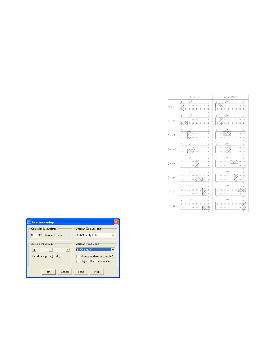
The RI-1 does not support a full cross point switch on the auxiliary buss.
This means that if you are going to connect the RI-1 to another RI-1 or RI-
300, you will use jumper blocks need to select the input and output channels
on the auxiliary buss. Use the diagram to the right to assist on jumper
placement of each channel.
When deciding on setting jumpers, you must first decide on what channels
you will be using. If you will be connecting an RI-300 to the RI-1, the RI-
300 is default to output on channel 1 and the RI-1 is default on channel 8.
You would then install a jumper on pins 1 and 2 so that the RI-1 can listen
to the RI-300. You then place a jumper on pins 15 and 16 so that the RI-
300 can listen to the RI-1.
All jumpers are placed in combination of one for AUX-IN and one for
AUX-OUT. You should never place multiple jumpers for the AUX-IN or
AUX-OUT.
After you have placed the jumpers, you then use System Commands 34 and
35 to enable and disable the input and output. You can also use the
programming software (PS-3) to adjust these default values. Click System
and Auxiliary Setup.