Connecting multiple repeater controllers together – Pacific Research Solutions RI-1 User Manual
Page 32
Pacific Research Solutions
RI-1 and PE-1 User Manual
Page 26
SECTION 9
AUXILIARY BUSS
The RI-1 has auxiliary input and output capability for connecting other RI-xxx repeater controllers together, or connecting to a
single control receiver. Additional controllers will allow interconnection of multiple repeaters, remotes, links or a repeater with
links and remotes. The Aux buss has eight audio channels and a digital serial data path to provide all the communication that is
required when connecting multiple controllers together. For added protection, the serial data communication protocol contains
an error check routine. If a controller does not receive valid data within four seconds, that controller will return to a normal
operating mode. This feature is designed to prevent a transmitter from staying keyed-down because of a serial data
communication failure.
CONNECTING MULTIPLE REPEATER CONTROLLERS TOGETHER
You can connect multiple RI-300 and/or RI-1 repeater controllers
together using the auxiliary buss connector and a standard 16 pin
flat cable. The cable should be pin to pin. Up to eight controllers
can exist on one cable and the cable should have an overall length
of no more than 6 feet. The auxiliary port has 8 audio channels in
a full cross point configuration. This means that any controller can
be connected to any other controller without interrupting other
controllers on the buss. All controllers will exchange audio, PTT
and command information. The PTT and S-Command information
is sent between the controllers as serial data. A fixed data time-out
timer is included in this protocol to protect against accidentally
keying a transmitter. If data is not received for four seconds, the
controllers will return to a normal operating mode. Any RI-300
and/or RI-1 controller attached to the buss can operate as a
repeater, remote or link. This architecture of an independent
controller for each radio port ensures maximum flexibility and
reliable operation of your system.
Auxiliary Buss and Programming Software
The auxiliary buss is disabled when using the programming port on any controller attached to the auxiliary buss, and during
data transfer between the controller and your computer. The buss will be re-enabled when the data transfer is done.
Passing System Commands between Controllers
See section 12 and section 15 for more detailed information regarding this subject, passing systems commands between
controllers.
Command information is sent from one controller to another by writing macros with data telling the controller to send S-
Command information to another controller and not to process that S-Command within itself. To build a macro that will
process S-Commands within the local controller, follow all the normal procedures in this manual and in the “Programming User
Commands and Macros” section 12. To build a macro with S-Commands that will be processed by another RI-300 controller,
you simply insert an “Ax” (where “x” is a numeral from 1 to 9) before the S-Command and its data within the macro. All data
from the “Ax” through the “C” (S-Command separator) will be sent to the second controller. Each controller in the system will
be assigned its own controller number. When sending a command to another controller, all controllers with the same controller
number as the “A” number, will execute that S-Command. All “A1” controllers will respond to “A1” prefix macro data. All
“A3” assigned controllers will respond to the “A3” prefixed macro table data.
The controller number is also used to determine which audio channel that controller will use to output audio. You can then
select which controllers you want to interconnect by turning on the correct audio inputs.
Note: The “controller unit address” is set with S-Command 39 and can be any address 1 through 9. The default address for
the RI-1 and PE-1 is 8. Each controller on the buss will need to have its own unit address.
If using the RI-1, see section 6 for details on configuring the auxiliary audio channels.
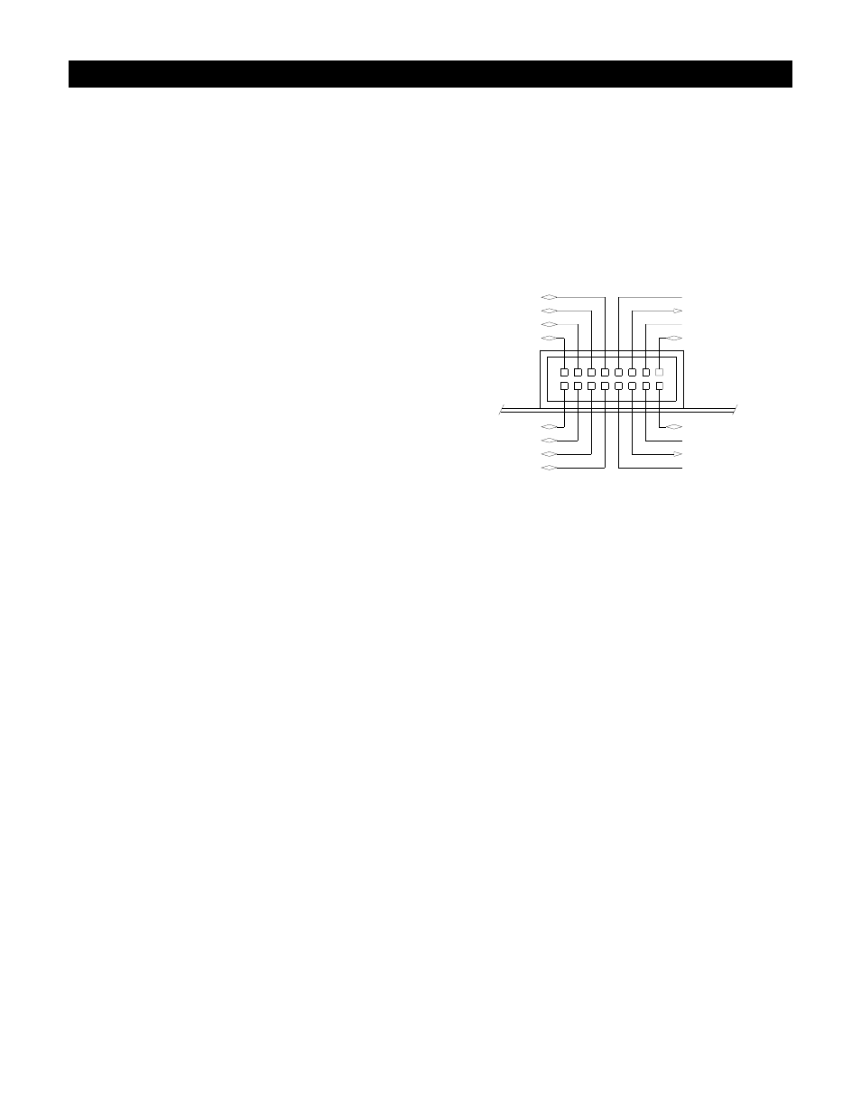
AUX-CH5
AUX-CH2
AUX-CH4
AUX-CH6
AUX-CH8
AUX-CH7
AUX-CH1
AUX-CH3
POWER GND
15
16
11
13
14 12
7
9
10
8
3
5
6
4
DIGITAL GROUND
+12VDC PWR OUT
POWER GND
IRQ/COS
S-DATA/TX
1
2
+12VDC PWR OUT
AUDIO GROUND
Auxiliary Interface Connector