Pacific Research Solutions RI-1 User Manual
Page 66
Pacific Research Solutions
RI-1 and PE-1 User Manual
Page 60
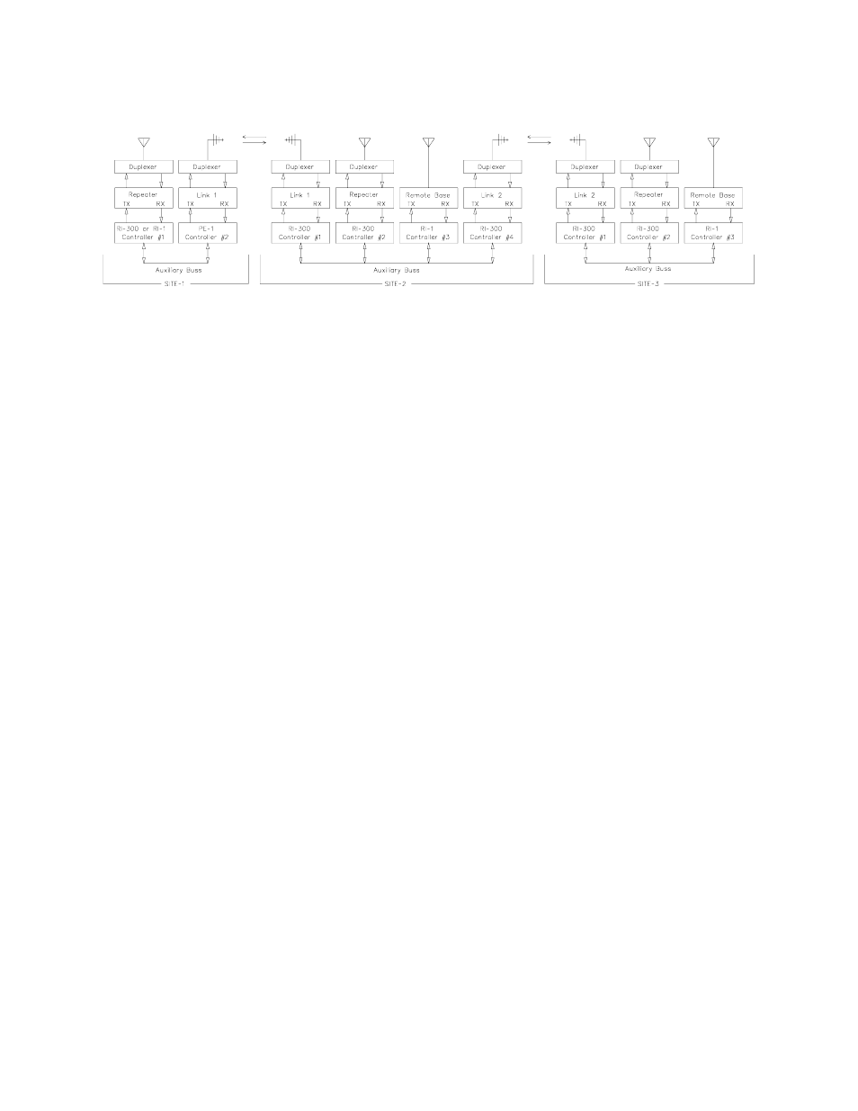
In our last example, we will use full duplex links between all sites. Each of these sites can include a repeater, remote base radio
and telephone. In this example, users can talk to each other and pass control functions from site to site. The traffic on this type
of link can be considered similar to a telephone party line. In this application, each repeater at each site can be connected or
disconnected from the links.
In systems like these, using the RI-300/RI-310 controller makes it possible to both use telephones and control remote base
radios between sites. Site 1 could even use a remote base radio on site 3 without interfering with the repeater operation of site
2. The RI-300 is so flexible that you can add or move links from any site without impact to the rest of the system.
THE CONTROLLER’S AUXILIARY BUSS ARCHITECTURE
The auxiliary buss is a passive, 16-pin flat cable on which you can attach up to 8 controllers. Each controller has eight audio
channels that are connected to the buss. Each channel of the buss will have a controller assigned to output audio on that
channel. S-Command 39 controls this audio channel assignment. A controller that has been assigned address 1 will use
channel 1 of the audio buss. This is the channel on which the controller will output audio onto the buss. In this type of
architecture, each controller on the auxiliary buss acts as PORT to the system. Each port is simply an input and output
connection between a radio and the system. Then within the controller, each port can be configured to operate as a repeater,
link or remote base. Because you can add ports or controller to the system as needed, the system can grow to meet the needs.
Controller settings vary based on the type of port configuration that the controller is assigned. There are primarily three
different controller/port configurations.
Repeater port
This is the main controller for the system. This is typically a full duplex port on which the users access
the system.
Link port
This is typically a full duplex port that is used to link sites together.
Remote Base port
This is typically a simplex radio that can be used to communicate with other repeaters or simplex mobile
users.
There are mainly 3 System commands used to configure the above modes.
S-Command 01
Controls the operation of the repeater function of the main port.
S-Command 34
Controls the operation of the audio out on the auxiliary buss from the local receiver.
S-Command 35
Controls the operation of the audio in from the auxiliary buss to the local transmitter.
The auxiliary buss also has serial data and buss request signals. Each controller on the bus will send packets of information
about itself to the buss. This information is used by other controller to determine when to accept and pass audio from the buss
to their transmitter. S-Commands from one controller to another may also be included in these packets. The buss has a buss
request signal. This signal is used to help keep the controller’s data packets from crashing into each other.
Even though the auxiliary buss has only 8 audio channels, you may notice that S-Command 39 will allow you to assign a 9
th
address. This feature allows you to attach a 9
th
controller to the buss that will not require any audio interaction but you still can
send and receive system commands from this 9
th
controller.