Configuration guide, System monitor mode – SoundTraxx SurroundTraxx User Manual
Page 31
SurroundTraxx User’s Guide
Configuration Guide Page 2:2
SurroundTraxx User’s Guide
Configuration Guide Page 2:3
numerical selection, for example, entering in a four-digit locomotive address,
pushing the knob in will cause the far left digit to flash. This indicates the
number to be changed. Turn the knob to change the value and push the knob
to select it. The next number to the right will now flash and so on, moving
from left to right until all the adjustments have been made. Pushing the knob
in before changing the value in the flashing digit will move it over to the next
digit. If you find a sub menu you desire to not change simply turn the knob to
the right to move to the next option.
System Monitor Mode
When you are not actively working within the menus, SurroundTraxx operates
in System Monitor mode, which provides visual status indicators for the six
audio channels. This is the most common mode during normal operation, and
SurroundTraxx automatically exits the menus to System Monitor mode after
several seconds of inactivity.
The central feature of System Monitor mode is a six-channel volume units
(VU) meter as shown below. The VU meter shows the volume level of each
channel; the more pixels displayed for a given channel, the higher the sound
level. When at least one, but not all, of the locomotives are muted, the letter
V appears at the far left of the display.
Mute
Icon
1 2 3
4 5 6
When the entire system is muted, the word
–MUTE– appears on the display.
See page 2:30 for more information on the mute function.
Audio clipping is a condition in which the level of one or more channels
exceeds the system’s capability. Because clipping is a form of waveform
distortion, it can negatively impact the sound quality of the affected channels.
An exclamation mark (
!) to the left of the VU meter indicates a clipping
condition; when this occurs, you may adjust the sound mixer parameters to
resolve the problem. See page 2:12 for details.
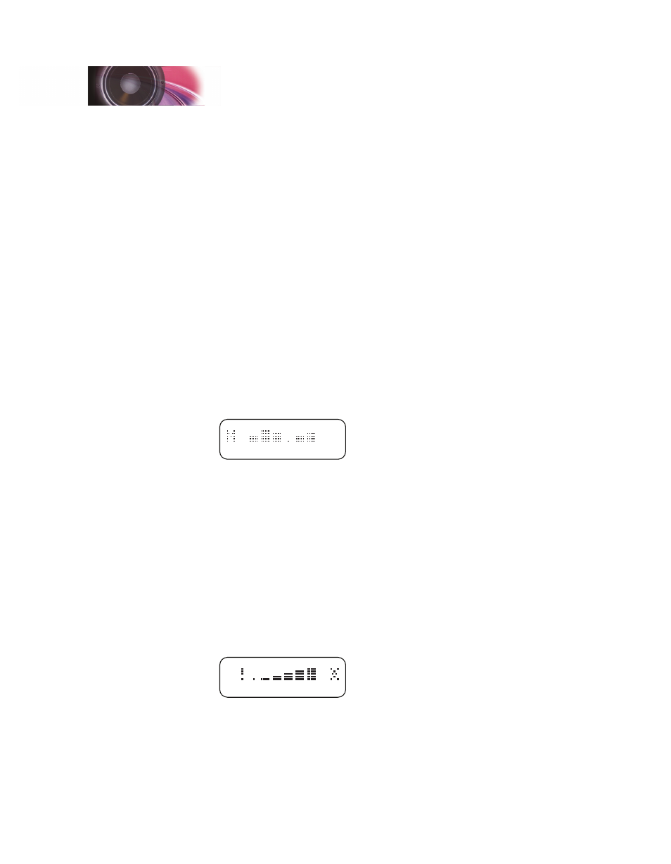
A network activity indicator at the far right side of the display appears each
time a valid network packet is received. Both this indicator (in the shape of a
starburst) and the clipping indicator are shown below.
VU Level (dB)
-48 -24 -12 -6 -3 0
Network
Activity
Clip
Configuration Guide