Configuration guide, Function mapping – SoundTraxx SurroundTraxx User Manual
Page 46
SurroundTraxx User’s Guide
Configuration Guide Page 2:18
SurroundTraxx User’s Guide
Configuration Guide Page 2:19
between speakers stays with the model as it travels between zones.
4. Once you've finished entering the scale mph, turn the knob until the
display shows ACCEL: 000 (Acceleration Rate). Select this with the
control knob and enter the acceleration rate as set in CV 3 of the mobile
decoder. CV 3 sets the baseline momentum to simulate the train’s
acceleration due to train weight, and sets how fast your locomotive will
respond to increases to throttle settings.
5. Turn the knob again until the display shows BRAKE:000 (Braking Rate).
Select this and enter the braking rate as set in CV 4 of your mobile
decoder. CV 4 sets the braking rate and controls how quickly the train will
respond to decreases in throttle settings.
It is important to make sure the values in CVs 3 and 4 of the mobile
decoder and those in your SurroundTraxx unit match, or the sound can
be 'ahead' or 'behind' the model if momentum isn’t taken into account.
Both CVs can be programmed with values between 0 and 255, with
255 corresponding to the slowest acceleration and braking rate. Lower
settings will yield a more responsive locomotive, which is useful for
switching or passenger consists. When both CVs are set to 0, the
locomotive will respond nearly instantly to any throttle changes. A setting
of 255, on the other hand, will require several minutes for a locomotive to
reach full speed from a standing stop.
Function Mapping
Function mapping allows SurroundTraxx to be reconfigured so that sound
effects and function outputs can respond to a different function key input.
This is especially useful for users who have throttles with less then thirteen
function keys. You can pick and choose what functions you can control
instead of being restricted to an arbitrary assignment
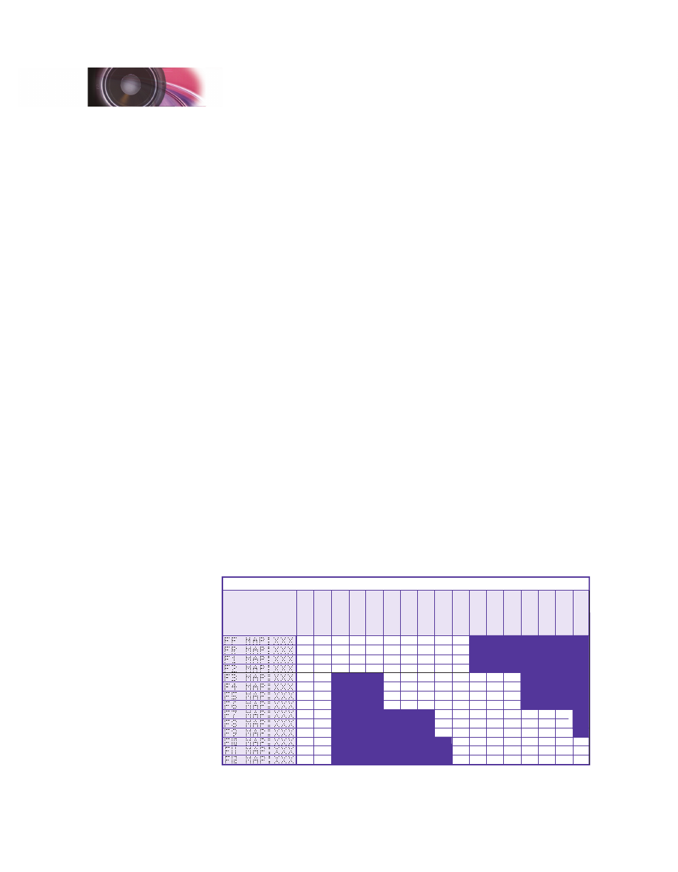
There are fourteen function-mapping settings. They are used to assign
output control to function keys F0(f) through F12 respectively. The default
function mapping for steam locomotives is listed below:
33
34
35
36
37
38
39
40
41
42
43
44
45
46
128
128
128
128
16
16
16
16
2
2
2
1
1
1
64
64
64
64
8
8
8
8
1
1
1
32
32
32
32
4
4
4
4
X
16
16
16
16
2
2
2
2
X
8
8
8
8
1
1
1
1
X
4
4
4
4
2
2
2
2
1
1
1
1
32
32
32
32
4
4
4
2
2
2
64
64
64
64
8
8
8
4
4
4
128
128
128
128
16
16
16
8
8
8
X
X
X
32
32
32
16
16
16
64
64
64
32
32
32
128
128
128
64
64
64
128
128
128
Contr
ol CV
F0 (f)
F0 (r)
F1
F2
F3
F4
F5
F6
F7
F8
F9
F10
F11
F12
Function
K
ey
Reserved
Reserved
Whistle
Bell
Shor
t Whistle
Hiss
Reserved
Reserved
Dynamo
Reserved
Steam Function Mapping Table
Reserved
MUTE
Reserved
Reserved
Coupler
Bold Numbers indicate default settings.
Configuration Guide