Alarm setup, Step 7 – complete configurator, Menu option – Super Systems 9120 User Manual
Page 15
4574 - SSi 9120 Manual Rev A
Page 15
Super Systems Inc
Note: Relay 1 through Relay 8 are display-only and cannot be modified from this screen
.
Relay Output Terminals
Relay Output 1 – terminals 7 and 8
Relay Output 2 – terminals 7 and 9
Relay Output 3 – terminals 7 and 10
Relay Output 4 – terminals 7 and 11
Relay Output 5 – terminals 7 and 12
Relay Output 6 – terminals 7 and 13
Relay Output 7 – terminals 7 and 14
Relay Output 8 – terminals 7 and 15 NC
Relay Output 8 – terminals 7 and 16 NO
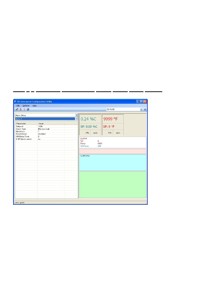
Step 7 – Complete Configurator
Alarm Setup
Menu Option
Note: This menu item is also located later in the manual under the
Section 1 – 9120 Configurator Menus
section
.
The 9120 controller can be
configured to use three different
alarms. Each of the alarms consists
of an alarm setpoint, alarm type,
alarm hysteresis, smart alarm, ON
delay time, and a 0 SP blocks alarm
value. The alarms come from the
factory with a default configuration
dependent on the application but
also can be modified prior to
shipment to your facility or in the
field by a supervisor.
Setpoint
This value is the setpoint for the
alarm. Clicking on this value will
display an input box from which the
user can select a new value. The
range is from –9999 to 9999.
Alarm Type
This value is the type of alarms
used. Clicking on this value will
display an input box with two (2)
drop-down lists from which the user can select a new value.
The values in the first (top) list box are:
PV 1 Value
PV 2 Value
PV 3 Value
Input 1 Value
Input 2 Value
Input 3 Value
PO1 Value
PO2 Value
PO3 Value
The values in the second (bottom) list box are: