Alarm setup – Super Systems 9120 User Manual
Page 34
4574 - SSi 9120 Manual Rev A
Page 34
Super Systems Inc
Range = 400
Example: if 4 – 20 mA = 800 mV - 1200 mV and PV is O2
Offset = 800 (starting point)
Range = 4000 (400.0)
Example: if 4 – 20 mA = 800 mV - 1200 mV and PV is % Carbon
Offset = 800 (starting point)
Range = 40000 (400.00)
O2 Exponent Range
This menu option will allow the user to set the Oxygen exponent range. The range is 0 to 10.
The 9120 controller has the option of using eight relay outputs. All of the relays have a positive common terminal and
independent negative terminals. All of the relays are configured in a normally closed position except relay number eight,
which has both a normally closed (NC) and a normally open (NO) terminal.
Note: Relay 1 through Relay 8 are display-only and cannot be modified from this screen
.
Relay Output Terminals
Relay Output 1 – terminals 7 and 8
Relay Output 2 – terminals 7 and 9
Relay Output 3 – terminals 7 and 10
Relay Output 4 – terminals 7 and 11
Relay Output 5 – terminals 7 and 12
Relay Output 6 – terminals 7 and 13
Relay Output 7 – terminals 7 and 14
Relay Output 8 – terminals 7 and 15 NC
Relay Output 8 – terminals 7 and 16 NO
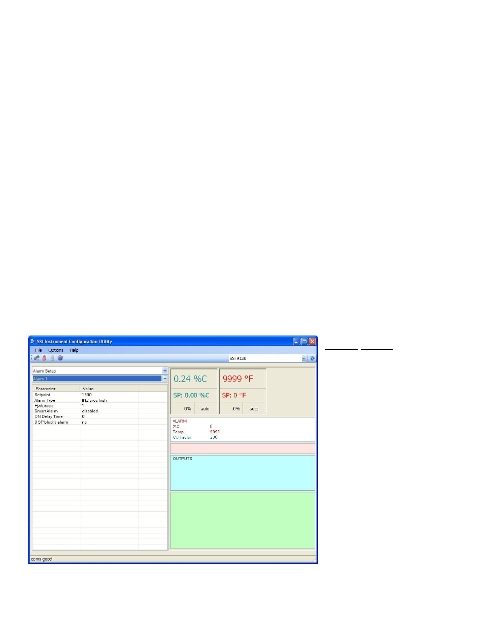
Alarm Setup
The 9120 controller can be
configured to use three different
alarms. Each of the alarms consists
of an alarm setpoint, alarm type,
alarm hysteresis, smart alarm, ON
delay time, and a 0 SP blocks alarm
value. The alarms come from the
factory with a default configuration
dependent on the application but
also can be modified prior to
shipment to your facility or in the
field by a supervisor.
Setpoint
This value is the setpoint for the
alarm. Clicking on this value will
display an input box from which the
user can select a new value. The
range is from –9999 to 9999.
Alarm Type
This value is the type of alarms