Eneo PNR-5304/4TB User Manual
Page 15
Part 1 – Introduction
15
• Video In/Ext. Port
This port does not support PoE. It's possible to establish
a network with network cameras and external hubs
using a Cat6 cable.
• This port is only available in Recorders with 8/16
channels.
• Green LED on the right will turn on if connected to
a 1000 BASE-T network. Orange LED on the left will
then flash once a link has been established.
• When using a Cat5e cable, the data transfer speed
may decrease depending on how to establish a
network.
eSATA Connection
Connect external hard drives to these ports.
Do not connect or disconnect an eSATA device while
the NVR is powered on. To connect an eSATA device,
first turn off the NVR and unplug the power cable.
Connect the eSATA device and then power the eSATA
device first and then NVR back on. To disconnect an
eSATA device, first turn off the NVR and unplug the
power cable. Turn off the eSATA device and then
disconnect the eSATA connection cable.
Network Connection
This NVR is capable of connecting to networks via an
ethernet connector. Connect an RJ-45 cable (Cat5,
Cat5e, or Cat6) to the NVR's network port. It's possible to
operate and upgrade the NVR remotely over a network.
Fore more information on ethernet connection setup,
refer to Network Setup on page 51.
Green LED on the right will begin to flash if connected
a 1000 BASE-T network. Orange LED on the left will
then flash once a link has been established.
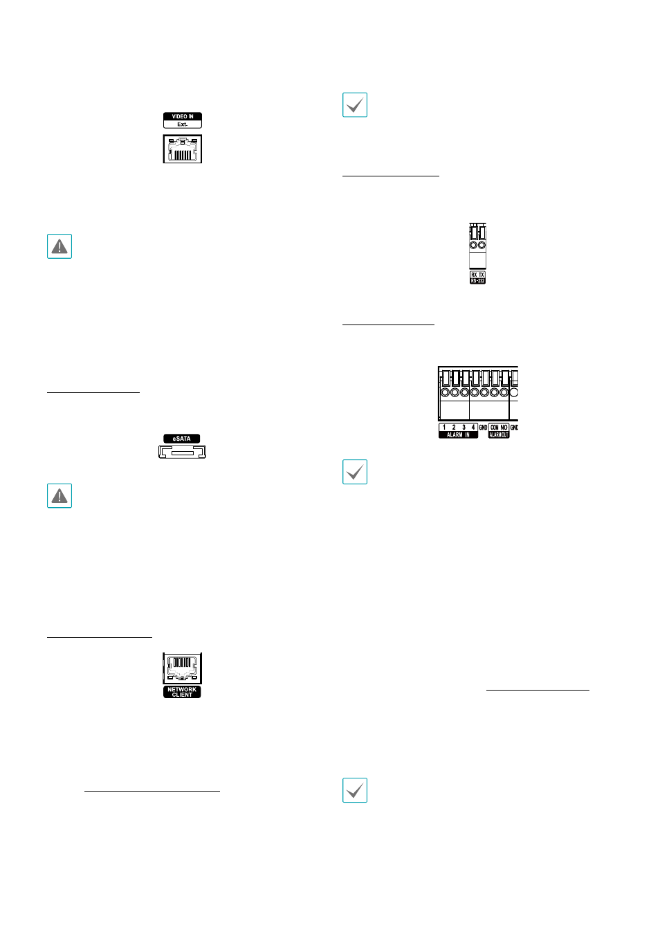
RS-232 Connection
Connect an external device such as a POS unit to this
port.
Alarm Connection
Connect alarm connectors to these ports.
Press down on the button and insert the cable into
the opening. Release the button and then pull on the
cable slightly to ensure it is held securely in place. To
disconnect the cable, press down on the button again
and pull the cable out.
• Alarm In 1 through 4
This NVR is capable of responding to event signals
from external alarm in devices. Connect mechanical
or electrical switches to AI 1 through 4 and the GND
(ground) connector. In order to be recognized by the
NVR, the signal from an alarm in device must be less
than 0.3V and maintained for at least 0.5 seconds. The
alarm in voltage range is 0V to 5V. For more information
on alarm in setup, refer to the Alarm-In on page 48.
• GND (Ground)
Connect alarm in or out's ground cable to the GND
connector.
All connectors marked "GND" are common connectors.