Configuration procedure – H3C Technologies H3C S12500 Series Switches User Manual
Page 139
123
Configure a routing policy on Switch A to filter route 10.5.1.0/24.
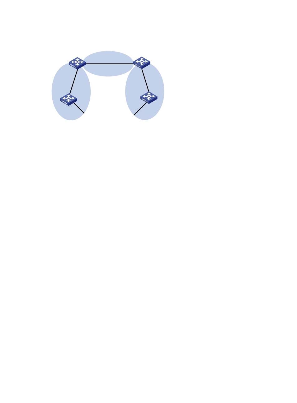
Figure 49 Network diagram
Configuration procedure
1.
Configure IP addresses for interfaces. (Details not shown.)
2.
Configure basic OSPF (see "
3.
Configure OSPF to redistribute routes:
# On Switch C, configure a static route destined for network 3.1.1.0/24.
<SwitchC> system-view
[SwitchC] ip route-static 3.1.1.0 24 10.4.1.2
# On Switch C, configure a static route destined for network 3.1.2.0/24.
[SwitchC] ip route-static 3.1.2.0 24 10.4.1.2
# On Switch C, configure a static route destined for network 3.1.3.0/24.
[SwitchC] ip route-static 3.1.3.0 24 10.4.1.2
# On Switch C, configure OSPF to redistribute static routes.
[SwitchC] ospf 1
[SwitchC-ospf-1] import-route static
[SwitchC-ospf-1] quit
# Display the OSPF routing table on Switch A.
<SwitchA> display ip routing-table
Routing Tables: Public
Destinations : 12 Routes : 12
Destination/Mask Proto Pre Cost NextHop Interface
3.1.1.0/24 O_ASE 150 1 10.2.1.2 Vlan200
3.1.2.0/24 O_ASE 150 1 10.2.1.2 Vlan200
3.1.3.0/24 O_ASE 150 1 10.2.1.2 Vlan200
10.1.1.0/24 Direct 0 0 10.1.1.1 Vlan200
10.1.1.1/32 Direct 0 0 127.0.0.1 InLoop0
10.2.1.0/24 Direct 0 0 10.2.1.1 Vlan200
10.2.1.1/32 Direct 0 0 127.0.0.1 InLoop0
10.3.1.0/24 OSPF 10 4 10.1.1.2 Vlan100
10.4.1.0/24 OSPF 10 13 10.2.1.2 Vlan200
10.5.1.0/24 OSPF 10 14 10.1.1.2 Vlan100
Area 0
Area 1
Area 2
Switch C
Vlan-int100
10.1.1.2/24
Vlan-int100
10.1.1.1/24
Vlan-int300
10.4.1.1/24
Vlan-int200
10.2.1.2/24
Switch B
Vlan-int400
10.3.1.1/24
Vlan-int400
10.3.1.2/24
Switch A
Vlan-int200
10.2.1.1/24
Vlan-int500
10.5.1.1/24
Switch D