Configuration procedure – H3C Technologies H3C S12500 Series Switches User Manual
Page 302
286
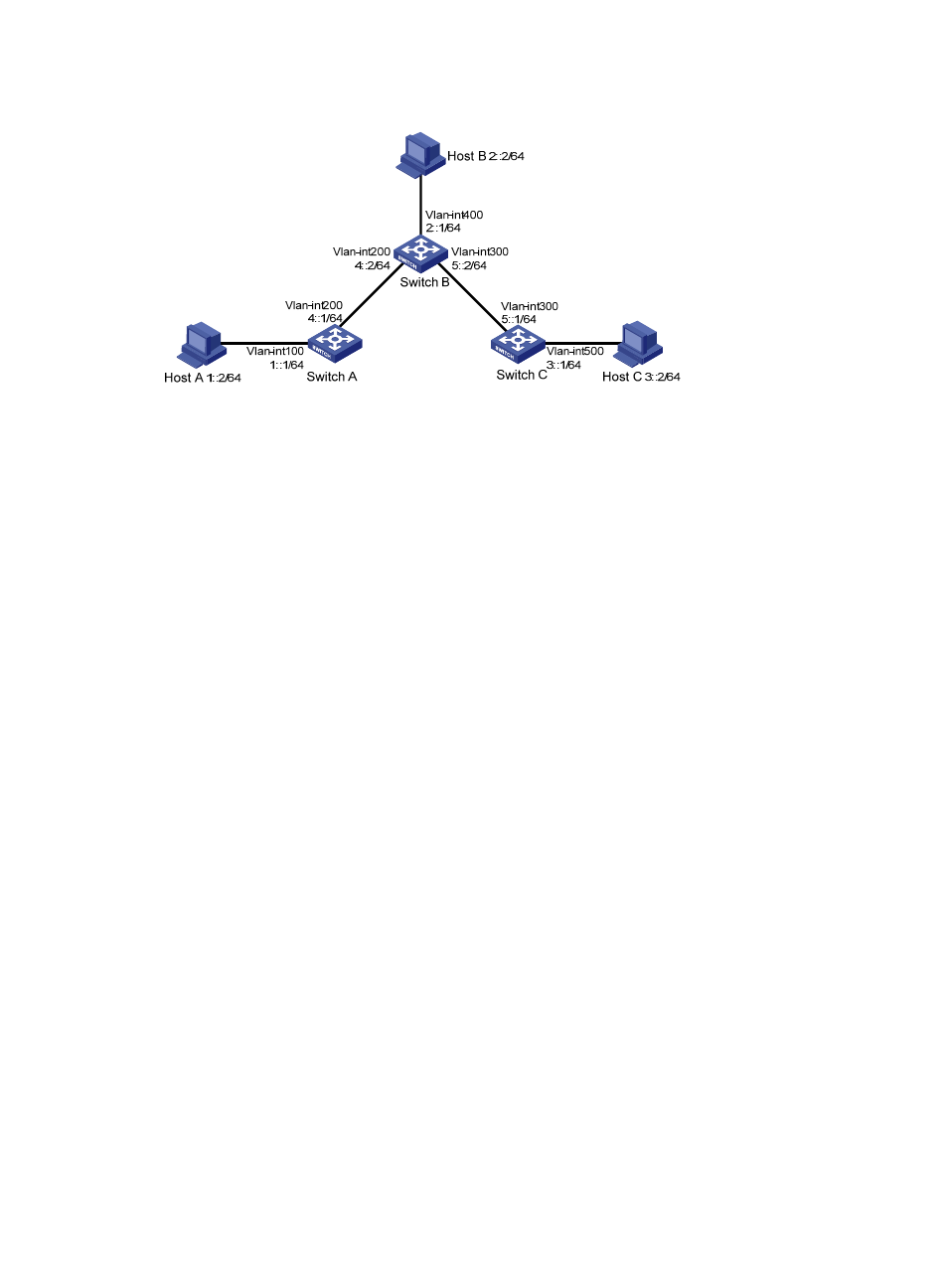
Figure 100 Network diagram
Configuration procedure
1.
Configure IPv6 addresses for all VLAN interfaces. (Details not shown.)
2.
Configure IPv6 static routes:
# Enable IPv6 and configure the IPv6 static route on Switch A.
<SwitchA> system-view
[SwitchA] ipv6
[SwitchA] ipv6 route-static :: 0 4::2
# Enable IPv6 and configure two IPv6 static routes on Switch B.
<SwitchB> system-view
[SwitchB] ipv6
[SwitchB] ipv6 route-static 1:: 64 4::1
[SwitchB] ipv6 route-static 3:: 64 5::1
# Enable IPv6 and configure the IPv6 static route on Switch C.
<SwitchC> system-view
[SwitchC] ipv6
[SwitchC] ipv6 route-static :: 0 5::2
3.
Configure the IPv6 addresses of all the hosts based upon the network diagram, and configure the
default gateway of Host A, Host B, and Host C as 1::1, 2::1, and 3::1.
4.
Verify the configuration:
# Display the IPv6 routing table on Switch A.
[SwitchA] display ipv6 routing-table
Routing Table : Public
Destinations : 5 Routes : 5
Destination: :: Protocol : Static
NextHop : 4::2 Preference: 60
Interface : Vlan-interface200 Cost : 0
Destination: ::1/128 Protocol : Direct
NextHop : ::1 Preference: 0
Interface : InLoop0 Cost : 0