Configuration procedure – H3C Technologies H3C S12500 Series Switches User Manual
Page 277
261
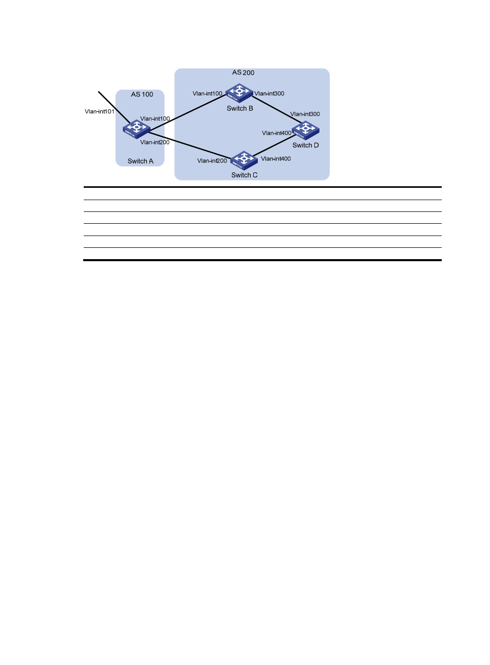
Figure 93 Network diagram
Device Interface
IP
address
Device
Interface IP
address
Switch A
Vlan-int101
1.0.0.0/8
Switch D
Vlan-int400
195.1.1.1/24
Vlan-int100
192.1.1.1/24
Vlan-int300 194.1.1.1/24
Vlan-int200
193.1.1.1/24
Switch C
Vlan-int400 195.1.1.2/24
Switch B
Vlan-int100
192.1.1.2/24
Vlan-int200
193.1.1.2/24
Vlan-int300
194.1.1.2/24
Configuration procedure
1.
Configure IP addresses for interfaces. (Details not shown.)
2.
Configure OSPF on Switch B, C, and D:
# Configure Switch B.
<SwitchB> system-view
[SwitchB] ospf
[SwitchB-ospf] area 0
[SwitchB-ospf-1-area-0.0.0.0] network 192.1.1.0 0.0.0.255
[SwitchB-ospf-1-area-0.0.0.0] network 194.1.1.0 0.0.0.255
[SwitchB-ospf-1-area-0.0.0.0] quit
[SwitchB-ospf-1] quit
# Configure Switch C.
<SwitchC> system-view
[SwitchC] ospf
[SwitchC-ospf] area 0
[SwitchC-ospf-1-area-0.0.0.0] network 193.1.1.0 0.0.0.255
[SwitchC-ospf-1-area-0.0.0.0] network 195.1.1.0 0.0.0.255
[SwitchC-ospf-1-area-0.0.0.0] quit
[SwitchC-ospf-1] quit
# Configure Switch D.
<SwitchD> system-view
[SwitchD] ospf
[SwitchD-ospf] area 0
[SwitchD-ospf-1-area-0.0.0.0] network 194.1.1.0 0.0.0.255
[SwitchD-ospf-1-area-0.0.0.0] network 195.1.1.0 0.0.0.255
[SwitchD-ospf-1-area-0.0.0.0] quit
[SwitchD-ospf-1] quit
3.
Configure BGP connections: