Configuration procedure – H3C Technologies H3C S12500 Series Switches User Manual
Page 63
47
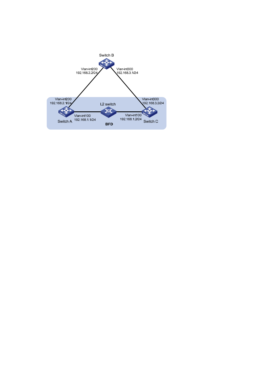
Switch C and the route information received from Switch C. Then, Switch A learns the static route sent by
Switch C, with the output interface being the interface connected to Switch B.
Figure 15 Network diagram
Configuration procedure
1.
Configure IP addresses for interfaces. (Details not shown.)
2.
Configure basic RIP:
# Configure Switch A.
<SwitchA> system-view
[SwitchA] rip 1
[SwitchA-rip-1] version 2
[SwitchA-rip-1] undo summary
[SwitchA-rip-1] network 192.168.1.0
[SwitchA-rip-1] quit
[SwitchA] interface vlan-interface 100
[SwitchA-Vlan-interface100] rip bfd enable
[SwitchA-Vlan-interface100] quit
[SwitchA] rip 2
[SwitchA-rip-2] version 2
[SwitchA-rip-2] undo summary
[SwitchA-rip-2] network 192.168.2.0
[SwitchA-rip-2] quit
# Configure Switch B.
<SwitchB> system-view
[SwitchB] rip 1
[SwitchB-rip-1] version 2
[SwitchB-rip-1] undo summary
[SwitchB-rip-1] network 192.168.2.0
[SwitchB-rip-1] network 192.168.3.0
[SwitchB-rip-1] quit
# Configure Switch C.
<SwitchC> system-view
[SwitchC] rip 1
[SwitchC-rip-1] version 2