Network requirements, Configuration procedure – H3C Technologies H3C S12500 Series Switches User Manual
Page 433
417
via FE80::7D58:0:CA03:1, cost 1, tag 0, A, 18 Sec
Dest 20::/32,
via FE80::7D58:0:CA03:1, cost 1, tag 0, A, 8 Sec
Dest 40::/32,
via FE80::7D58:0:CA03:1, cost 1, tag 0, A, 3 Sec
Applying a routing policy to filter received BGP routes
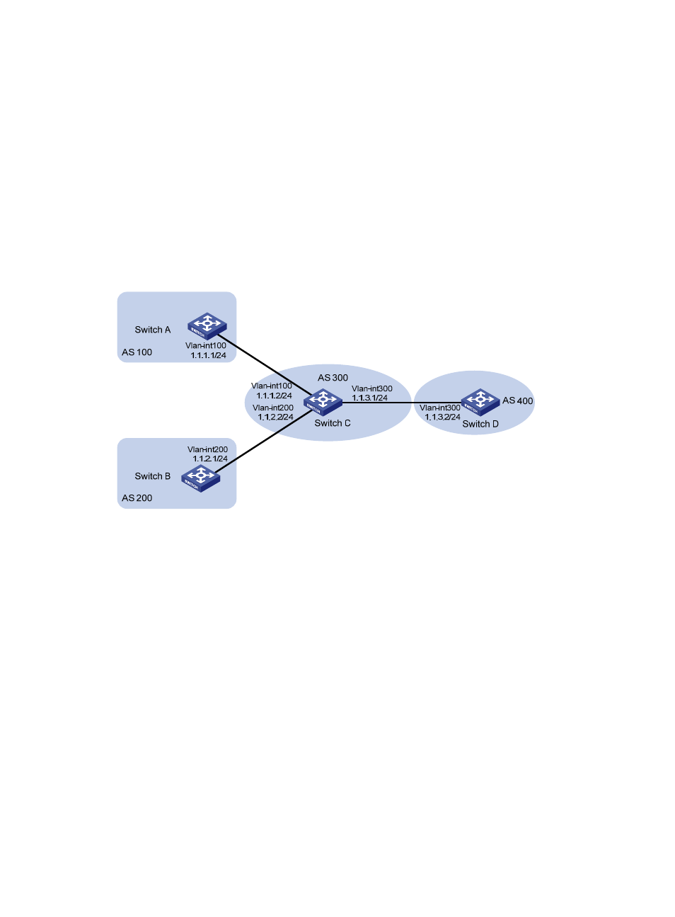
Network requirements
All the switches in
run BGP. Switch C establishes EBGP connections with other switches.
Configure a routing policy on Switch D to reject routes from AS 200.
Figure 126 Network diagram
Configuration procedure
1.
Configure IP addresses for the interfaces. (Details not shown.)
2.
Configure BGP:
# Configure Switch A.
<SwitchA> system-view
[SwitchA] bgp 100
[SwitchA-bgp] router-id 1.1.1.1
[SwitchA-bgp] peer 1.1.1.2 as-number 300
# Configure Switch B.
<SwitchB> system-view
[SwitchB] bgp 200
[SwitchB-bgp] router-id 2.2.2.2
[SwitchB-bgp] peer 1.1.2.2 as-number 300
# Configure Switch C.
<SwitchC> system-view
[SwitchC] bgp 300
[SwitchC-bgp] router-id 3.3.3.3
[SwitchC-bgp] peer 1.1.1.1 as-number 100