Network requirements, Configuration procedure – H3C Technologies H3C S12500 Series Switches User Manual
Page 416
400
--- 2::2 ping statistics ---
5 packet(s) transmitted
5 packet(s) received
0.00% packet loss
round-trip min/avg/max = 2/2/4 ms
Telnet uses TCP, and ping uses ICMP. The preceding results indicate that all TCP packets of Switch
A are forwarded to next hop 1::2, and other packets are forwarded according to the routing table.
The PBR configuration is effective.
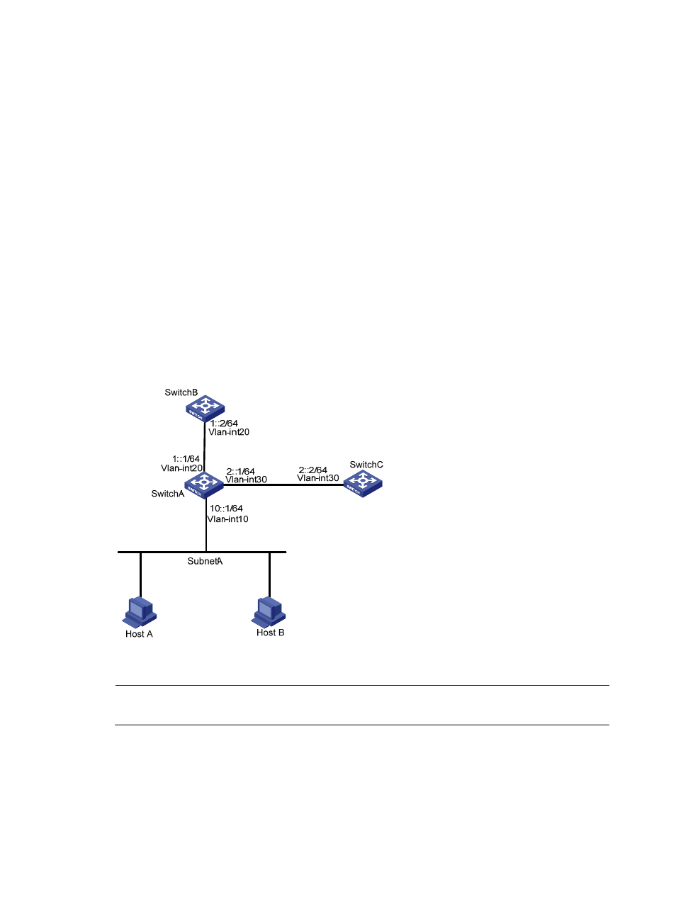
Configuring IPv6 interface PBR based on packet type
Network requirements
As shown in
, configure PBR on the VLAN-interface 10 of Switch A, so that TCP packets
arriving on VLAN-interface 10 are forwarded through next hop 1::2/64 and other IPv6 packets are
forwarded according to the routing table.
Switch A is directly connected to Switch B and Switch C. Switch B and Switch C are unreachable to each
other.
Figure 123 Network diagram
Configuration procedure
NOTE:
In this example, RIPng is configured to ensure the reachability among switches.
1.
Configure Switch A:
# Configure RIPng.
<SwitchA> system-view
[SwitchA] ipv6
[SwitchA] ripng 1
[SwitchA-ripng-1] quit