Bgp route reflector configuration, Network requirements, Configuration procedure – H3C Technologies H3C S12500 Series Switches User Manual
Page 271
255
# Display the routing table on Switch B.
[SwitchB] display bgp routing-table 9.1.1.0
BGP local router ID : 2.2.2.2
Local AS number : 20
Paths: 1 available, 1 best
BGP routing table entry information of 9.1.1.0/24:
From : 200.1.2.1 (1.1.1.1)
Original nexthop: 200.1.2.1
Community : No-Export
AS-path : 10
Origin : igp
Attribute value : MED 0, pref-val 0, pre 255
State : valid, external, best,
Not advertised to any peers yet
The route 9.1.1.0/24 is not available in the routing table of Switch C.
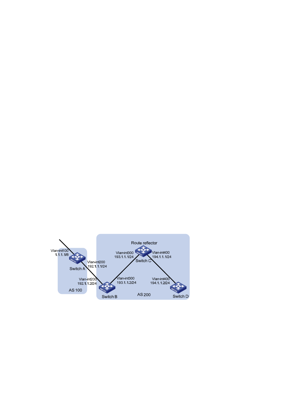
BGP route reflector configuration
Network requirements
In
, all switches run BGP.
•
EBGP runs between Switch A and Switch B. IBGP runs between Switch C and Switch B, and
between Switch C and Switch D.
•
Switch C is a route reflector with clients Switch B and D.
•
Switch D can learn route 1.0.0.0/8 from Switch C.
Figure 91 Network diagram
Configuration procedure
1.
Configure IP addresses for interfaces. (Details not shown.)
2.
Configure BGP connections:
# Configure Switch A.
<SwitchA> system-view
[SwitchA] bgp 100
[SwitchA-bgp] router-id 1.1.1.1