Configuration procedure – H3C Technologies H3C S12500 Series Switches User Manual
Page 59
43
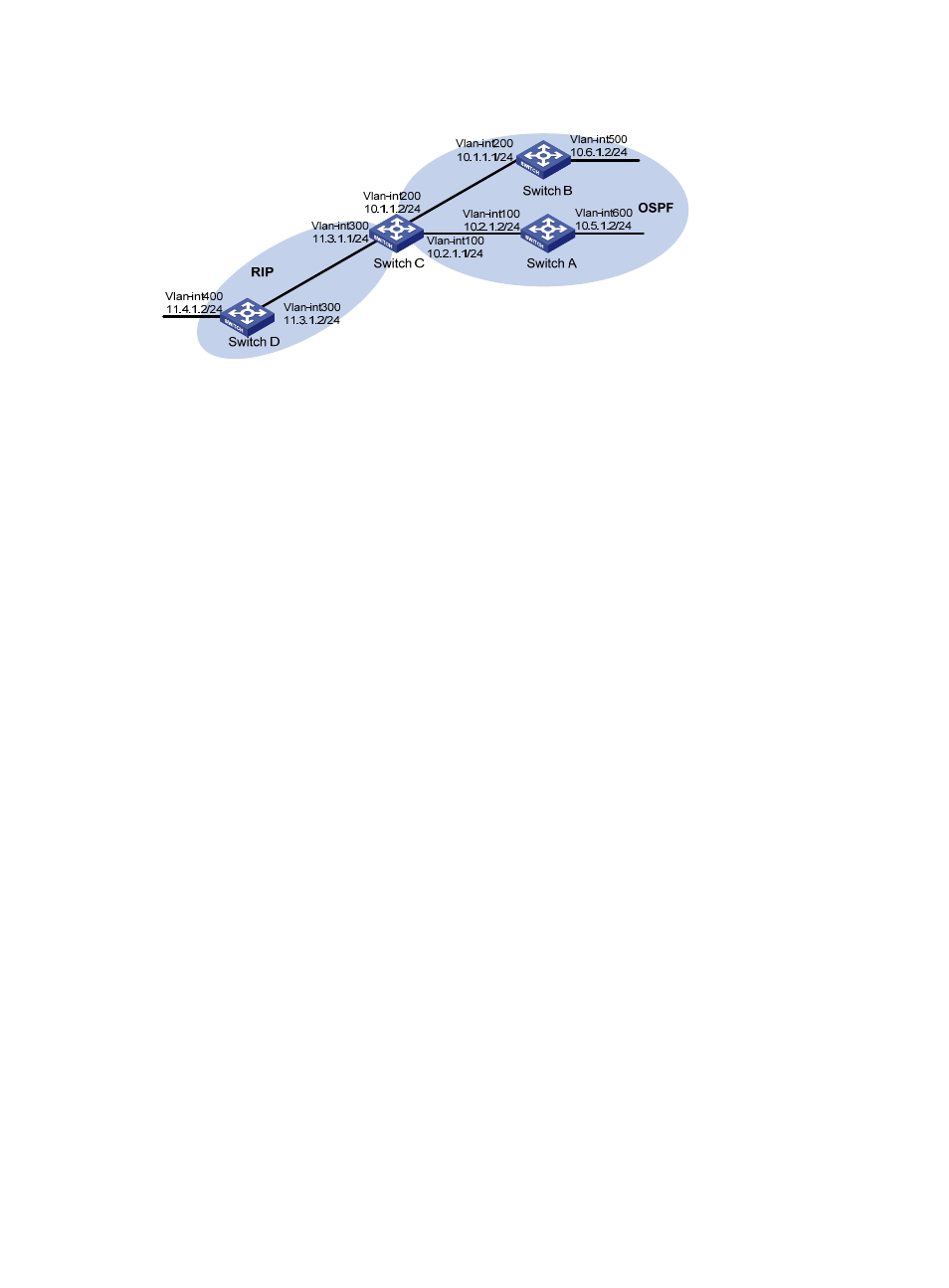
Figure 13 Network diagram
Configuration procedure
1.
Configure IP addresses for interfaces. (Details not shown.)
2.
Configure basic OSPF:
# Configure Switch A.
<SwitchA> system-view
[SwitchA] ospf
[SwitchA-ospf-1] area 0
[SwitchA-ospf-1-area-0.0.0.0] network 10.5.1.0 0.0.0.255
[SwitchA-ospf-1-area-0.0.0.0] network 10.2.1.0 0.0.0.255
[SwitchA-ospf-1-area-0.0.0.0] quit
# Configure Switch B.
<SwitchB> system-view
[SwitchB] ospf
[SwitchB-ospf-1] area 0
[SwitchB-ospf-1-area-0.0.0.0] network 10.1.1.0 0.0.0.255
[SwitchB-ospf-1-area-0.0.0.0] network 10.6.1.0 0.0.0.255
[SwitchB-ospf-1-area-0.0.0.0] quit
# Configure Switch C.
<SwitchC> system-view
[SwitchC] ospf
[SwitchC-ospf-1] area 0
[SwitchC-ospf-1-area-0.0.0.0] network 10.1.1.0 0.0.0.255
[SwitchC-ospf-1-area-0.0.0.0] network 10.2.1.0 0.0.0.255
[SwitchC-ospf-1-area-0.0.0.0] quit
3.
Configure basic RIP:
# Configure Switch C.
<SwitchC> system-view
[SwitchC] rip 1
[SwitchC-rip-1] network 11.3.1.0
[SwitchC-rip-1] version 2
[SwitchC-rip-1] undo summary
# Configure Switch D.
<SwitchD> system-view