H3C Technologies H3C S7500E Series Switches User Manual
Page 61
51
•
The fiber ports on some cards have dust plugs. Remove the dust plugs before using the fiber ports.
Keep the removed dust plugs for future use. Fiber ports must be installed with dust plugs when they
are not in use.
•
Fiber connectors are protected by dust covers. Remove the dust covers before using the fiber
connectors. Keep the removed dust covers for future use. Fiber connectors must be installed with dust
caps when they are not in use. Replace the dust cover if it is loose or polluted.
•
Before connecting a fiber, use dust free paper and absolute alcohol to clean the end face of the
fiber connector. You can brush the end face only in one direction. You also need to brush the end
face of the fiber port.
•
Never bend or curve a fiber when connecting it. After a fiber is installed, the bend radius must be
not less than 40 mm (the minimum dynamic bend radius is 20 D, and the minimum static bend
radius is 10 D. D indicates the outer diameter of dust caps).
•
If the fiber has to pass through a metallic board hole, the hole must have a sleek and fully filleted
surface (the filleting radius must be not less than 2 mm). When passing through a metallic board
hole or bending along the acute side of mechanical parts, the fiber must wear jackets or cushions.
•
Never use excessive force to the fiber connector. Never pull, press, or extrude the fiber fiercely. For
the allowed maximum tensile load and crush load, see "Appendix E Cables."
The installation of different optical fiber connectors is similar.
To connect your switch to the network through optical fibers:
1.
Install a transceiver module into the port.
2.
Remove the dust cover of the optical fiber connector, and clean the end of the optical fiber.
3.
Remove the dust plug of the transceiver module, connect one end of the optical fiber to the
transceiver module in the switch, and connect the other end into the transceiver module in the peer
device.
{
For how to connect an LC connector, see
.
{
For how to connect an MPO connector, see
.
4.
Examine the port LEDs for incorrect connection.
For more information about the LED status, see "Appendix C LEDs."
NOTE:
For the QSFP+ module, you do not need to differentiate between the transmitter (TX) and receiver (RX)
ports. For other types of transceiver modules, the Tx port on one end must connect to the RX port on the
other end.
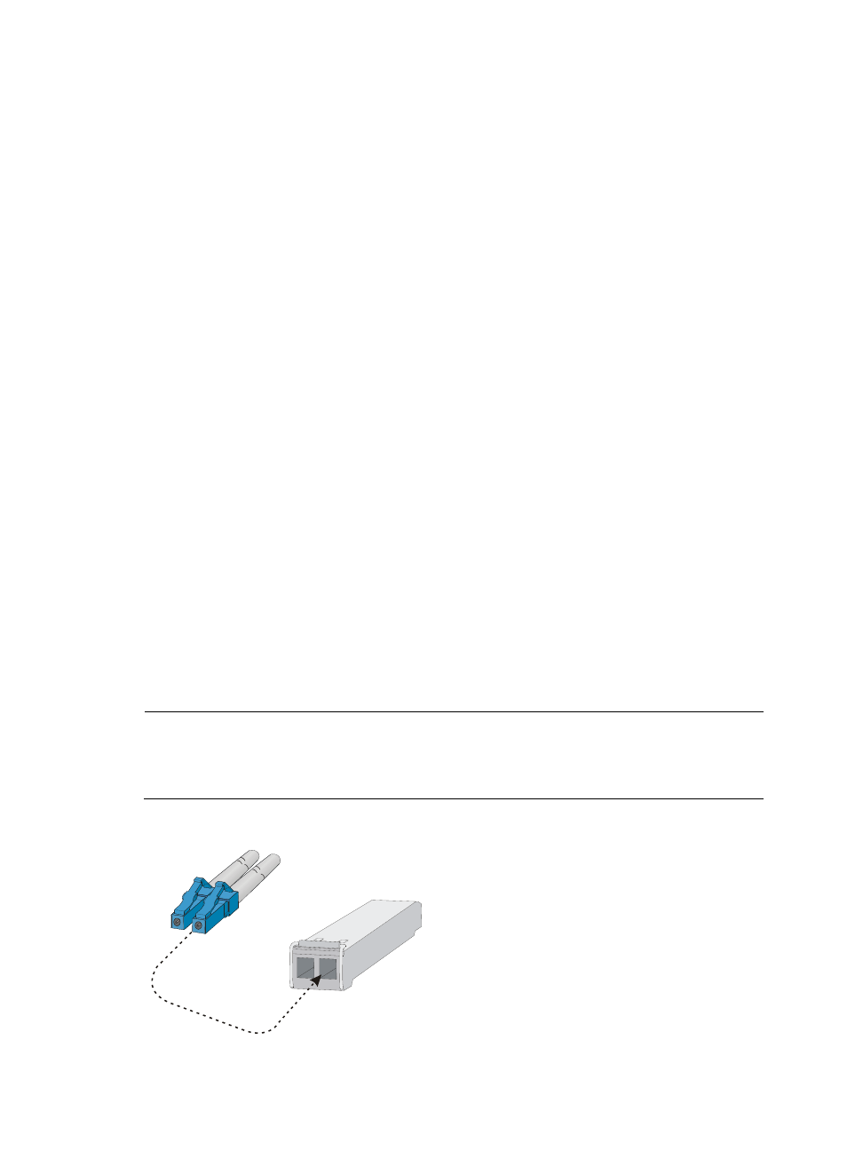
Figure 43 Using an LC optical fiber connector to connect an SFP module
LC plug
SFP module