Yaskawa i80M Connecting Manual User Manual
Page 160
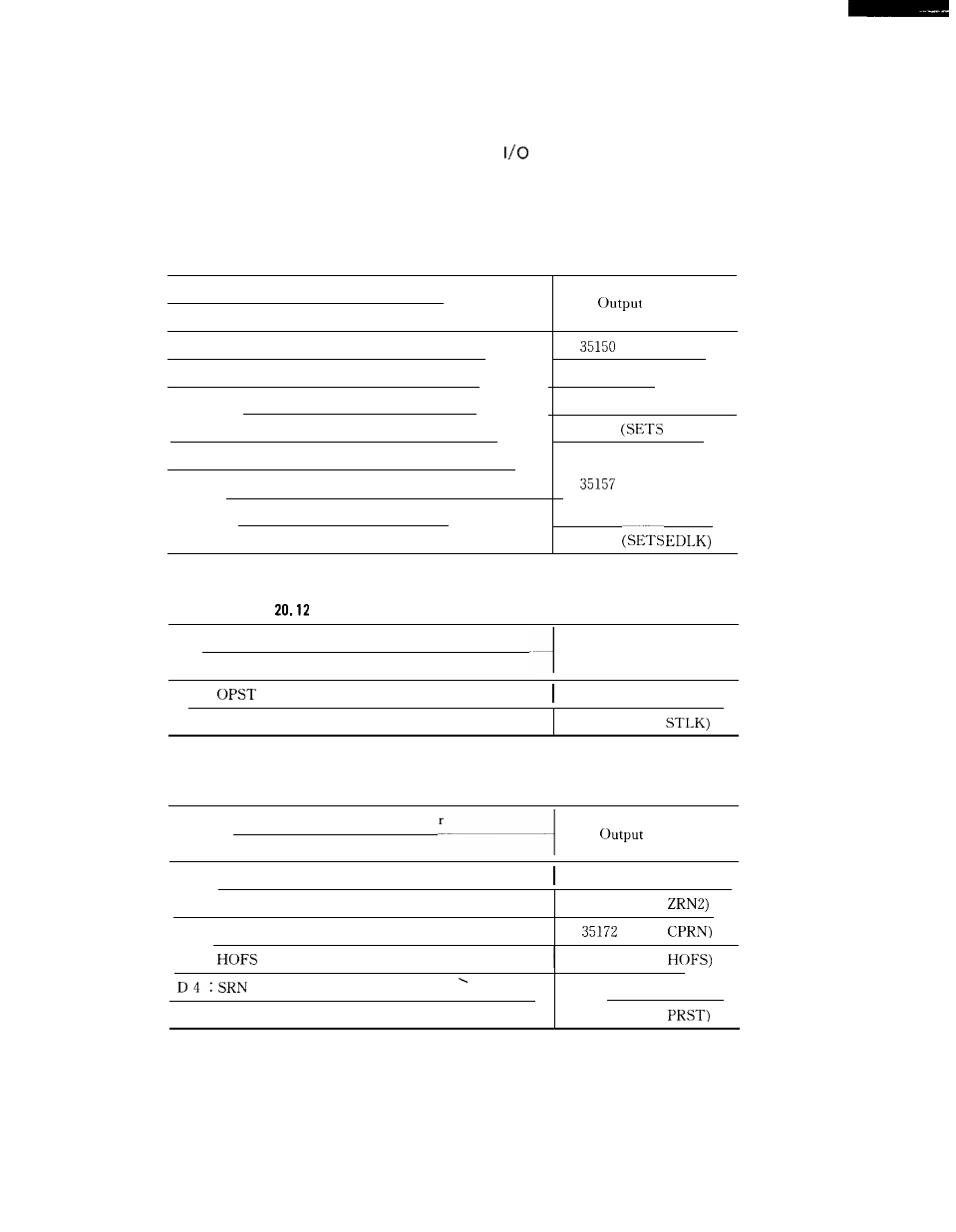
20.2.44 INTERNAL TOGGLE SWITCH MONITOR OUTPUTS (#3515- # 3518)
The setting parameter status can be delivered to the
and read by the PC.
The relationship between the parameters and output addresses is indicated below.
Table 20.11 Setting Parameter Number pm 0000 and Output Signals
Setting Parameter Number
pm 0000
D O : SBKT
Single-block switch
D 1 : MLKT
Machine lock switch
D 2 : DRNT
Dry Run switch
D 3 : B D T T
Block delete switch
D 4 : ABST
Manual absolute switch
--
D 5 : AFLT
Auxiliary function lock switch
D 6 : DLKT
Display lock switch
D 7 : INHET
Edit prohibit switch
Signals
#
(SETS SBK)
# 35156 (SETS MLK)
# 35154
(SETS DRN)
# 35382
BDT)
# 35151 (SETS ABS)
#
(SETS AFL)
# 35152 (SETS DLK)
# 35162
Table
Setting Parameter Number pm 0001 and Output Signals
Setting Parameter Number
Output Signals
pm
0001
D O :
Optional stop
#35383 (SETS OPT)
D 1 : STLKT
Start lock switch
# 35176 (SETS
Table 20.13 Setting Parameter Number pm 0005 and Output Signals
Setting Parameter Number
Signals
pm 0005
D O : Z R N
Manual zero return switch
#35160 (SETS ZRN)
D 1 : ZRN2
Manual second zero return switch
# 35161 (SETS
D 2 : CPRN
Machining interrupt point return switch
#
(SETS
D 3 :
Automatic mode handle offset switch
#35171 (SETS
Setup point return switch
. .
D 7 : PRST
Program restart switch
# 35167 (SETS SRN)
# 35153 (SETS
160