Yaskawa i80M Connecting Manual User Manual
Page 172
20.2.57 AXIS DETACHMENT INPUTS
# 30833
# 30834)
The axis detachment inputs are used to detach the fourth and fifth axes.
The detached axes are placed in the same status as in the machine lock state so that the servo
alarm conditions occurring on the detached axes are disregaraded.
NOTE
1.
Axis detachment must be carried out with the servo power turned
OFF. If the axis detachment inputs
are closed with
the servo power OFF, the alarm output
closes.
2. When a detached axis is reinstalled, the power must be turned OFF
and then ON again.
3. When detaching an axis, remove the components between the AC
Servopack (lamp) and AC servomotor. The components between the
FC300B circuit board and AC Servopack (lamp) cannot be removed (see
the equipment connection diagram).
4. If the axis detachment input is turned OFF after the servo power is
turned ON with an axis detached, the alarm output
closes.
5. As regards a detached axis, overtravel input (
+4/* +5, –4/
–5) detection does not take place.
6. As for a detached axis, the servo system does not turn ON.
fore, the sevo OFF signal
SV OF4/ SV OF5) is invalid.
20.2.58
COMMAND
# 36540 TO
# 36567) INPUTS
These signals are used to determine the speed of the spindle motor when the control is in the
state of S command 5-Digit Non-Contact output or S Command 5-Digit Analog output.
GR1 to GR4 (#31 100 to #31 103) are used to enter the control state of the gear range be-
tween the spindle and the spindle motor to determine the spindIe motor speed by the spindle
speed specified in the part program.
SINV input inverts the polarity of the analog output at the time of S command 5-Digit
Analog output. While the polarity is inverted,
signal is output. When M03 command
is executed, M04S contact is opened. When M04 command is started, M04S contact is closed.
(1)
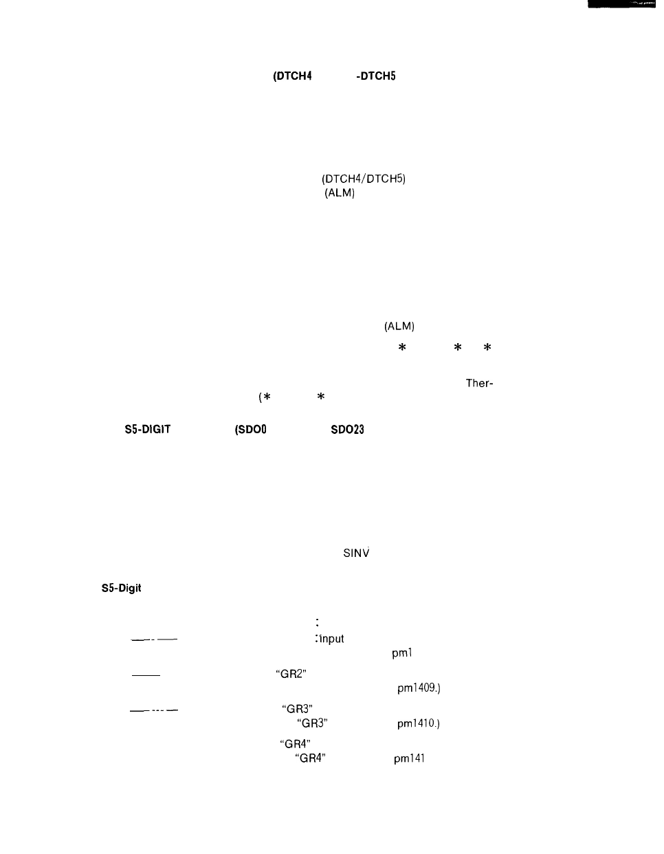
Command 24-Bit Non-Contact Output
Binary code 23 bits (O to 8388608= spindle motor speed) are output as follows by the spindle
motor speed command and GR1 through GR4
;The output when “GR1”
is closed. (Set the spindle motor maximum
speed at gear range “GR1” to parameter
408.)
— ; The output when
input is closed. (Set the spindle motor maximum
.
speed at gear range “GR2” to parameter
; The output when
input is closed. (Set the spindle motor maximum
speed at gear range
to parameter
— ; The output when
input is closed. (Set the spindle motor maximum
speed at gear range
to parameter
1.)
172