Yaskawa i80M Connecting Manual User Manual
Page 254
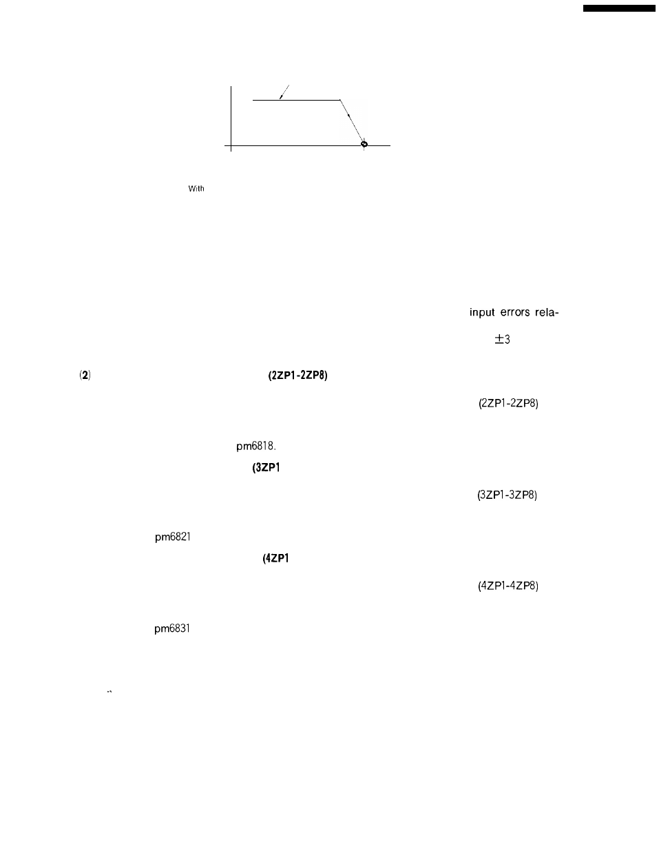
SPEED
RAPID TRAVERSE
Fig. 21.9
SPEED SEQUENCE
Note:
an appropriate parameter (Pm 4003), it is possible to use the grid method for the
second and subsequent reference return operations.
Second and Subsequent High-speed Reference Point Return Opera-
tions after Power ON
(1) Reference Point Outputs (ZP1-ZP8)
The ZP1 to
ZP
8 outputs are closed while the control axis stays at the reference point after com-
pletion of reference point return or reference point positioning. Due to inch
tive to the metric output system or metric input errors relative to the inch output system, howev-
er, the ZP1 to
ZP
8 outputs are actually closed while the control axis remains within
pulses of
the reference point.
Second Reference Point Outputs
When part program command G30 is executed in the automatic
machine at the second reference point, the second reference
closed.
operation mode to position the
point outputs
are
The second reference point is determined when the distance to the reference point is defined
by parameters pm6811 through
(3) Third Reference Point Outputs
-3ZP8)
When part program command G30P3 is executed in the automatic operation mode to position
the machine at the third reference point, the third reference point outputs
are
closed.
The third reference point is determined when the distance to the reference point is defined
by parameters
through pm6828.
(4)
Fourth Reference Point Outputs
-4zP8)
When part program command G30P4 is executed in the automatic operation mode to position
the machine at the fourth reference point, the fourth reference point outputs
are
closed.
The fourth reference point is determined when the distance to the reference point is defined
by parameters
through pm6838.
254