Yaskawa i80M Connecting Manual User Manual
Page 175
SPINDLE MOTOR
SPEED OUTPUT
SPINDLE
—SPEED
COMMAND
Fig. 20. 31
Analog Outputs When Spindle
Maximum/Minimum Speeds Clamped
NOTE
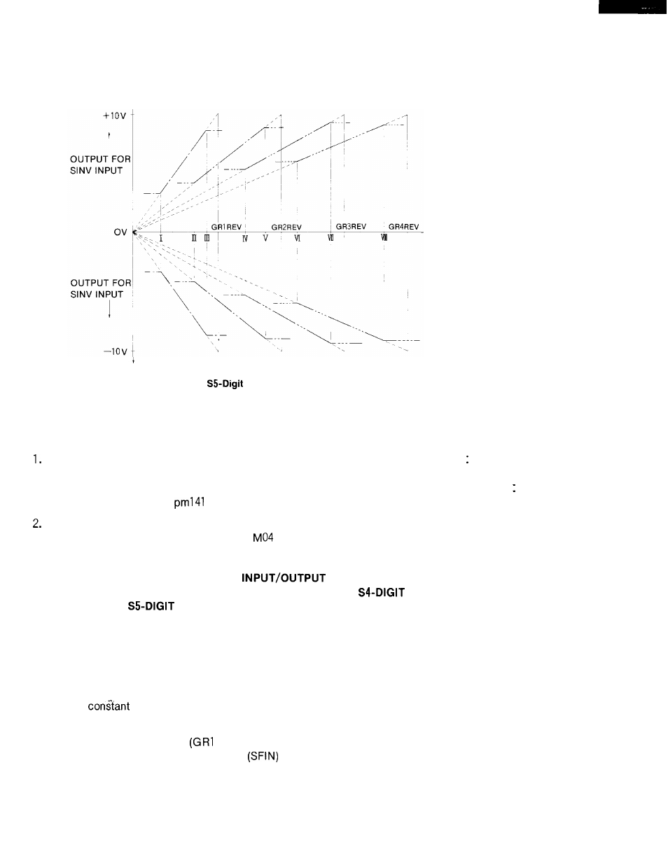
The spindle motor speed command output is obtained from the
(Spindle speed command) X (4095 or 10 V)
(4095 or 10 V output speed in spindle gear range determined by
parameters pm1408 through
1.)
following relation
GR1 through GR4 inputs
With the spindle motor speed motor analog output, the polarity may be inverted by proc-
essing M03 (spindle forward rotation) or
(spindle reverse rotation)within the control by
using parameter.
20.2.59 GEAR SELECTION COMMAND
(GR1 # 31100 to GR4 # 31103, GRIS
# 36504 to GR4S # 36507, SF # 36517, SFIN # 311 17)
NON-CONTACT OUT-
PUT OR
ANALOG OUTPUT
After executing S command, the control outputs SF signal and checks maximum gear speed
designation at the same time, and outputs gear selection command (GR1 S to GR4S) corres-
ponding to gear speed.
The control compares the output gear signal with current gear selection and sends back
SFIN when they meet.
If they are different, the control performs gear selection sequence.
When the
speed output is required for gear selection, GRO signal contact is closed.
The control immediately outputs constant speed corresponds to GRO.
Input gear input signal
to GR4) until gear selection is completed and send back
spindle gear selection completion signal
on completion of gear selection.
The control
outputs specified spindle speed command as non-contact or D/A output. Send back FIN sig-
nal when spindle speed agrees with command.
175