Yaskawa i80M Connecting Manual User Manual
Page 253
21. 3. 1. 21 REFERENCE POINT RETURN CONTROL
SIGNALS (ZRN # 30070, ZRN2
# 30072,
●
DC1 #
# 30737, ZP1 #
# 36307, 2ZP1 #36310-
2
ZP
8 # 36317, 3ZP1 # 36320 -3ZP8 # 36327, 4ZP1 # 36330 -4ZP8 # 36337)
NOTE: Signals other than the ZRN and ZRN2 signals are for servo axis control 1/0.
These
signals cause the machine to return to the specified mechanical reference point
upon control power ON.
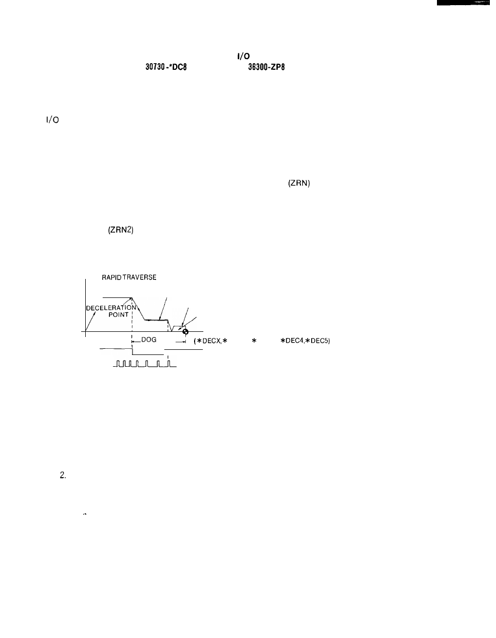
Reference point return is effected by the grid method. According to this method, the refer-
ence point is determined by the position detector zero point pulse (1 pulse/revolution).
When the manual jog mode is selected after power ON and the axes are moved in the refer-
ence point return direction with the manual reference point return input
closed, the refer-
ence point return operation is performed in accordance with Fig. 21.8 (as is the case with G28
execution in the automatic operation mode).
If the axes are moved in the reference point return direction with the second manual refer-
ence point return input
closed, the machine moves toward the second reference point,
decelerates, and stops.
SPEED
(Pm 2801 -Pm 2805)
APPROACH SPEED (Pm 2521 -Pm 2525)
/
CREEP SPEED (Pm 2531 -Pm 2535)
TRAVERSE DISTANCE (Pm 4451 -Pm 4455)
SPEED SEQUENCE
WIDTH
I
DECY, DECZ,
I
SPEED LS SIGNAL
--- ZERO POINT PULSE
Fig. 21.8 Reference Point Return Operation (Grid Method)
NOTE
1. For manual reference point return, the jog axis movement input must
be left closed.
Once high-speed reference point return (automatic/manual) is
effected, the subsequent return operations are carried out by positioning
the machine at the determined reference point.
2 5 3 .