Yaskawa i80M Connecting Manual User Manual
Page 168
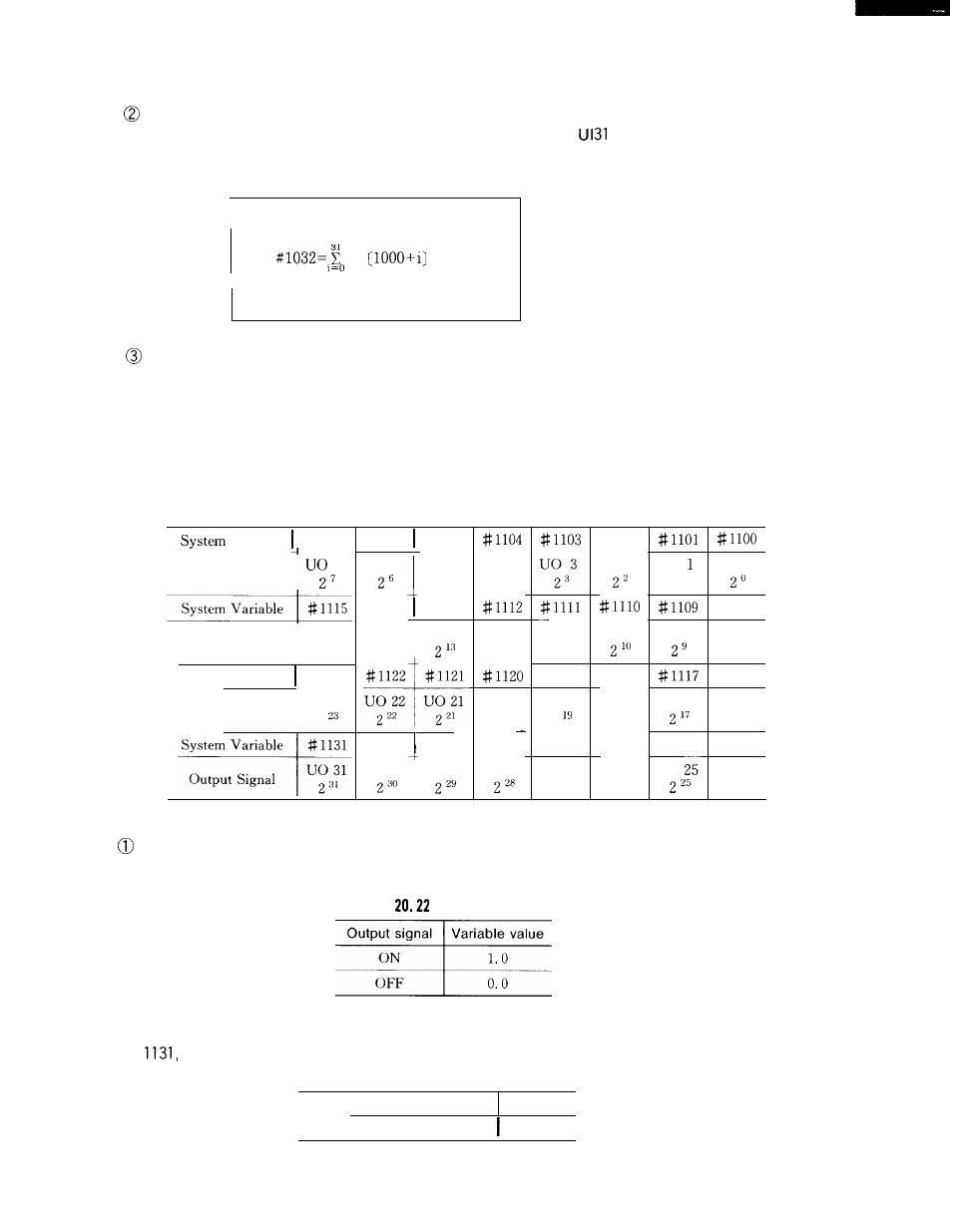
When system variable # 1032 is designated for the right-hand side of an operational ex-
pression, the above-mentioned 32-point input signal (UIO to
) are collectively read as a
decimal positive value.
#
x 2 ’
Numerical
values cannot be substituted with a system variable between # 1000 and #
1032 designated for the left-hand side of an operational expression.
(2) When an interface output system variable is designated for the left-hand side of an oper-
ational expression, the ON or OFF signal is delivered to the 32-point output signal specialized
to the microprogram.
The relationship between the output signals and system variables is indicated in Table 20.
21.
Table 20.21
Interface Output Signal and System Variable
Variable # 1107
Output Signal
7
Output Signal
Uo 15
2
15
1
System Variable # 1123
Output Signal
UO 23
2
# 1 1 0 6 #1105
UO 6
Uo 5
2
5
# 1 1 1 4 #1113
U o 1 4 U o 1 3
2
14
# 1 1 2 2 # 1 1 2 1
Uo 22 Uo 21
2
22
2
21
#1130 #1129
UO 30 UO 29
U o 4
2
4
Uo 1 2
2
12
Uo
20
2
20
# 1128
UO 28
Uo 11
2
11
#1119
Uo
19
2
#1127
UO 27
227
# 1102
U o 2
Uo 10
#1118
UO 18
218
#1126
UO 26
226
U o
2 ’
Uo 9
Uo 17
# 1 1 2 5
U O
Uo o
# 1108
UO 8
2
8
#1116
UO 16
216
#1124
UO 24
224
When the value 1.0 or O. 0 is substituted for a system variable in Table 20.21, the resul-
tant associated signal output is either ON or OFF,
Table
Variable value
. .
When a value other than 1.0 and O. 0 is substituted for a variable between # 1100 and #
it is handled as follows.
(Empty) or smaller than O. 5
0.0
Other than above
1.0
168