Yaskawa i80M Connecting Manual User Manual
Page 282
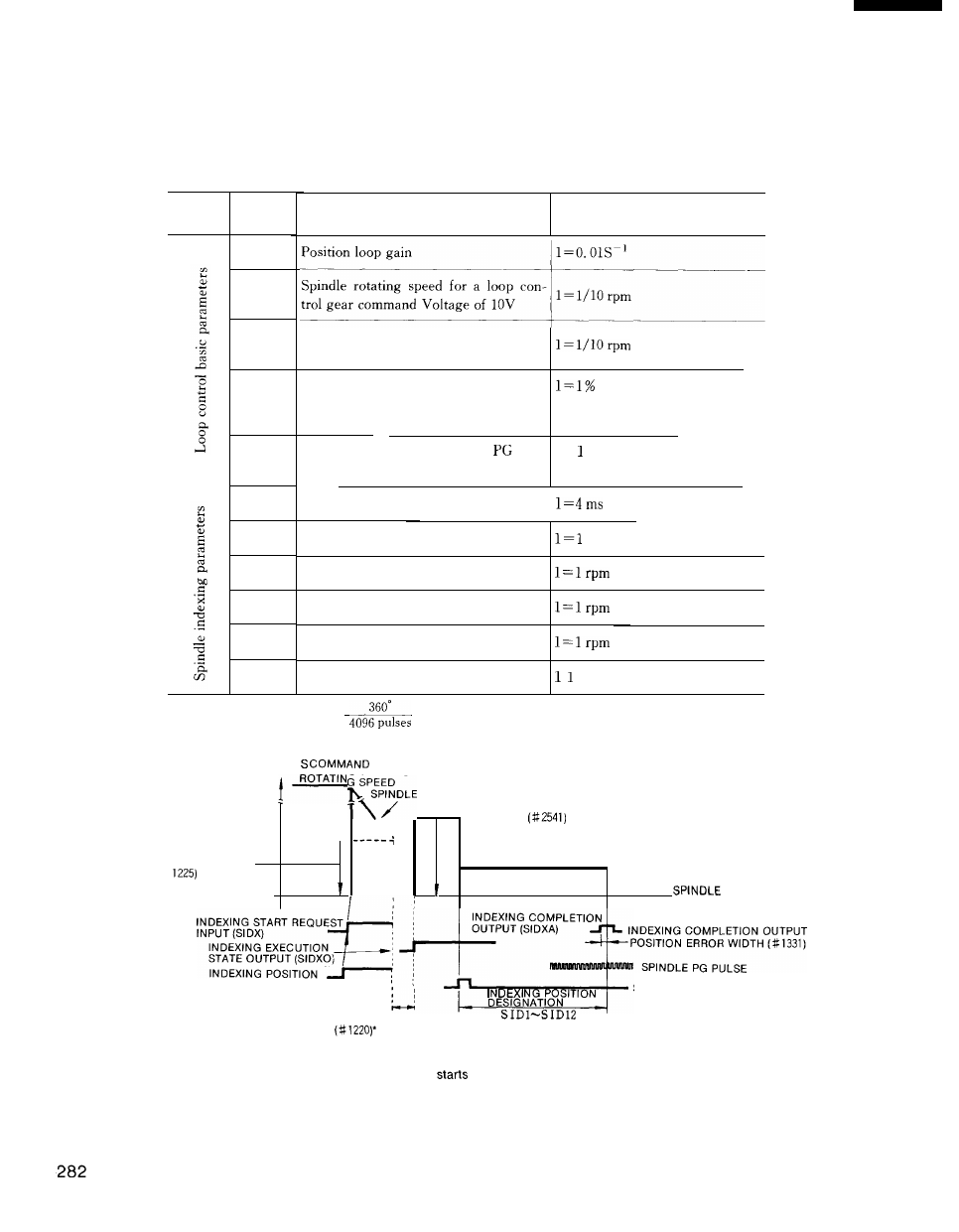
(4) Details of spindle indexing parameters and operations
The parameters listed in Table 21.23 are used for spindle indexing. The spindle indexing
operations are detailed in Fig. 21.21,
Table 21.23 Spindle Indexing Parameters and Operations Category
Category
Number
(name)
pm 1417
pm 1415
pm 1416
pm
1351
pm 1541
pm 1220
pm 1414
pm 2541
pm 2546
pm 1225
pm 1331
D e s c r i p t i o n
Setting unit
Spindle rotating speed for a loop con-
trol gear command Voltage of 10V
Maximum spindle rotating speed for
loop control
Servo error zone magnification for loop
[
Set the ration of the load to the
control
maximum spindle speed
1
Number of pulses per spindle
rota- 1 = pulse
rion
(Select a setting of 1024. )
Spindle stop verification timer
Spindle indexing zero point setup
pulse
Spindle indexing start speed command
Spindle indexing creep speed command
Spindle stop verification rotating speed
Spindle position error width
=
p u l s e
NOTE: 1 pulse= 0.088° (
]
SPINDLE ROTATING
SPEED COMMAND
BASED
ROTATING
SPEED INDEXING START
‘ \
1
SPEED
STOP VERIFICATION
ROTATING SPEED
(#
INDEXING TARGET POINT
CREEP ROTATING
SPEED (#2546)
ROTATION
‘ A N G L E
INDEXING POSITION
DESIGNATION INPUT
. .
ITION
SPINDLE PG ZERO POINT PULSE
DESIGNATION
SPINDLE STOP VERIFICATION
TIMER
Fig. 21.21 Details of Spindle Indexing Operations
●
The spindle stop verification timer
counting after verifying that the spindle rotating
speed
for stop verification (# 1225) is reached. If the spindle rotating speed deviates from
the stop verification rotating speed during timer counting, the count is reset. Counting
restarts when the stop verification rotating speed prevails again,
That is, the rotating
speed must not be higher than that specified during stop verification timer operation.