Yaskawa i80M Connecting Manual User Manual
Page 57
NC output control codes
– DC4 to start and stop the machine, but the machine can not out-
put control codes to control the NC.
However, when the machine under control is unable to
process data in time, it can control the CS signals of the NC to halt the data outputting of the
NC.
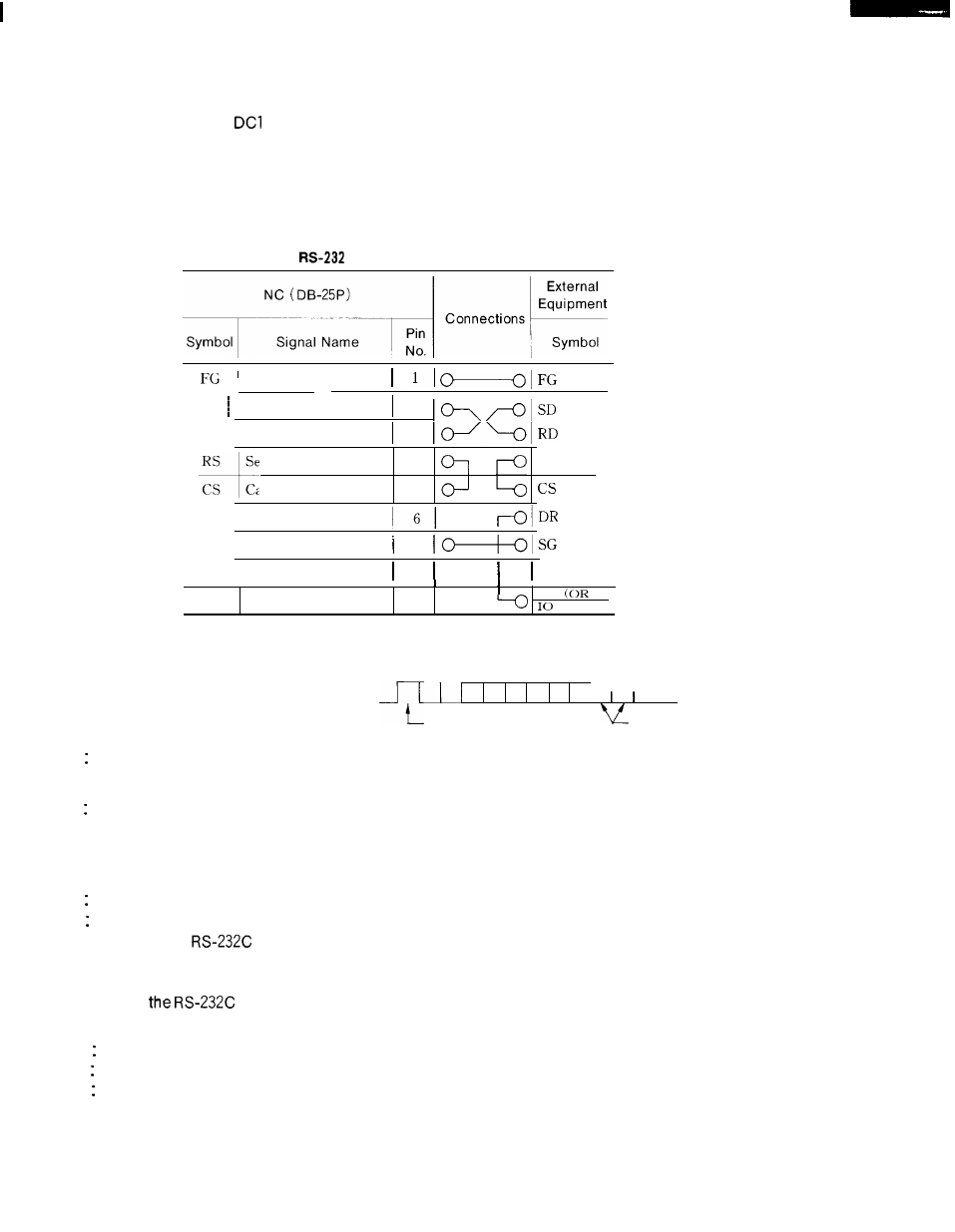
When CS signals of the NC are not used, short CS and RS as shown below.
Table 14.4
C Interface Connecting Cable (B)
Frame grounding
SD Sending data
2
RD
Receiving data
3
RS
Sending data
4
RS
C s
Capable of sending
5
DR
Data set ready
SG
Signal grounding
7
ER
Data terminal ready
20
I
E R
AI. ARM )
●
Description of signals
FG : Safety grounding
1
SD: Transmission data (output)
RD: Received data (input)
START
STOP
RS Request for sending (output) -When sending data, NC is turned on when starting transmis-
sion, and turned off when transmission ends.
CS For sending (input) -When this input signal is on, NC can send data. If the machine under
control is unable to process data in time, it can turn off this signal to interrupt the transmis-
sion
of data from NC within 2 characters.
shown in Table 14.4.
SG Signal grounding.
ER Data terminal ready-Use this signal as a
When this signal is not used, connect lines as
tape rewinding signal if a tape reader is con-
nected
Among
to an
interface. The tape reader can be rewound if this signal is ON,
NOTE
interface signals, the following are normally not used by the NC,
DR Data set ready
ER Data terminal ready
CD Data receiving carrier detection
However, when “1” is set for parameter
lock is added,
CHKDR ( # 6021 D4), a DR (data set ready) inter-
57