Yaskawa i80M Connecting Manual User Manual
Page 324
A8. 3.2 WIRING PRECAUTIONS
Servopack is
a device for speed control of 3000:1, and signal level of several mini-volts or less.
The following precautions should be taken for wiring.
(1) For signal lines and PG feedback lines, use twisted cables or multi-core shielded
pair cables (Yaskawa Drawing DE8400093).
Cable length is a maximum of 3 m for reference input lines and a maximum of 20 m for PG
feedback lines. Use the shortest possible length.
(2) For ground line, cable should be as heavy as possible to provide class
3 ground (ground re-
sistance 100 S2 or less).
Make sure to ground at one point.
If the motor and machine are insu-
lated, ground the motor.
(3) To prevent malfunction due to noise, take the following precautions:
. Place the noise filter, Servopack and
reference as near as possible to each other.
Make sure to insert a surge absorbing circuit into the relay, electromagnetic contact, and
solenoid coils.
Run the power line and signal line, holding the distance to 30 cm or more; do not run them in
the same duct or in a bundle.
●
When the same power is used for Servopack, as for an electric welder or electrical discharge
machine or when a high-frequency noise source is present in the vicinity, use filters in the pow-
er and input circuits.
The Servopack uses a switching amplifier, and spurious noise may be present in the signal
line. Never leave the termination of the analog input wiring open.
(4) Remedy for Radio Frequency Interference (R.
Servopack is not provided with protected from radio frequency interference.
If the controller is
adversely affected by radio waves, connect a noise filter to power supply.
(5) The signal line uses cables whose core is extremely fine
(O. 2 to 0.3
Avoid using ex-
cessive force which may damage these cables.
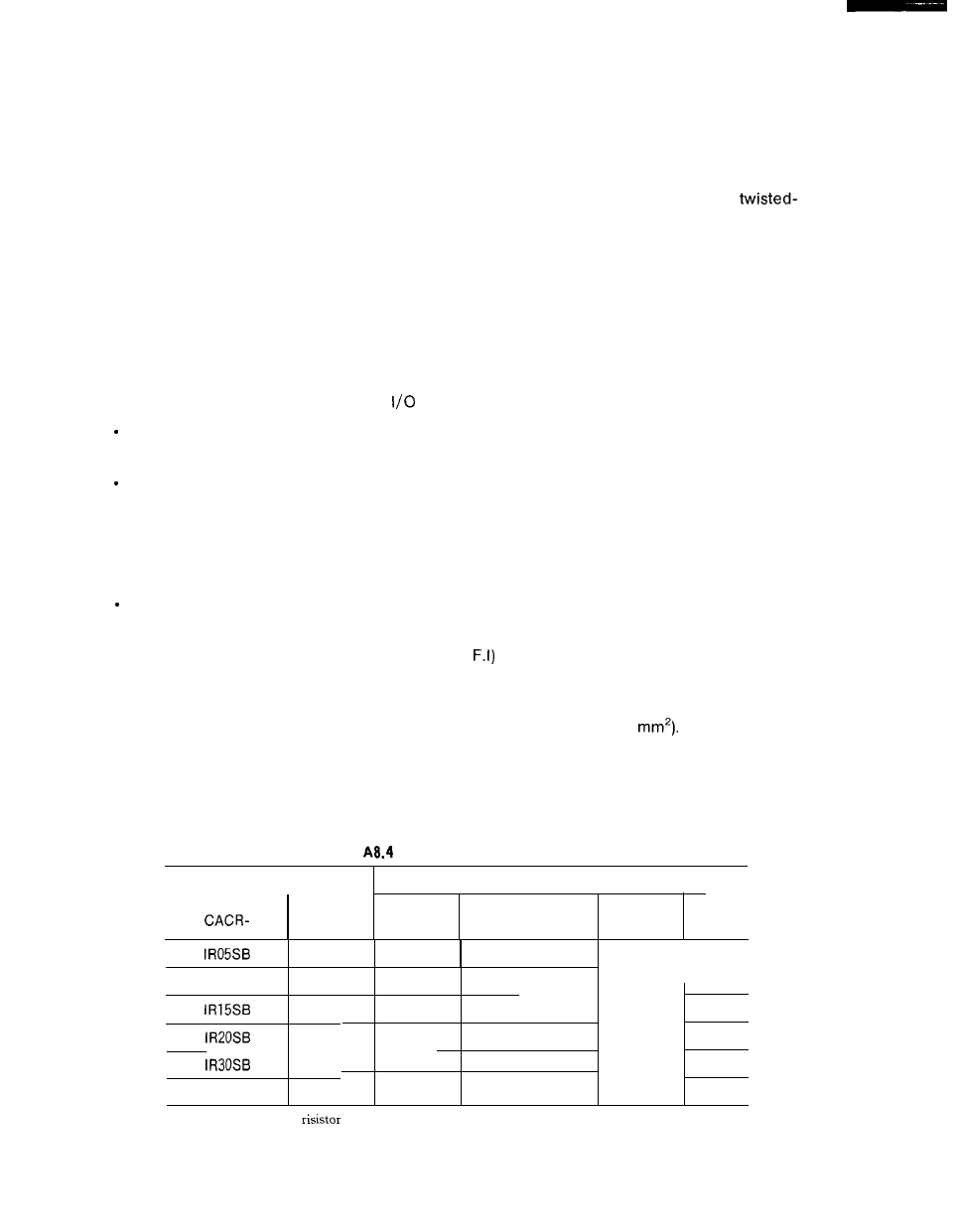
A8. 3.3 POWER LOSS
The power loss of Servopack is shown in Table A8. 4.
Table
Power Loss at Rated Output
Servopack
I
output
Power Loss
—
Type
Current
Main
Regenerative
Control
A
Circuit
Resistance
Circuit
Total
w
w
w
w
4.2
40
10
k
-
110
IR1OSB
7.6
70
20
150
. .
11.7
80
20
160
60
18.8
100
40
200
26.0
160
80
300
IR44SB
33.0
210
100
370
Note:
The regenerative
causes power loss when the motor is decelerated, but is negligible if the
motor is not started and stopped frequently.
324