Appendices, Menu list, Memory menu – Roland V-1HD+ Compact 4 x HDMI Video Switcher & UVC-01 USB Capture Device Kit User Manual
Page 30: Menu list” (p. 30)
30
Appendices
Menu List
* The menu is shown on the monitor connected to the PREVIEW connector (p. 9).
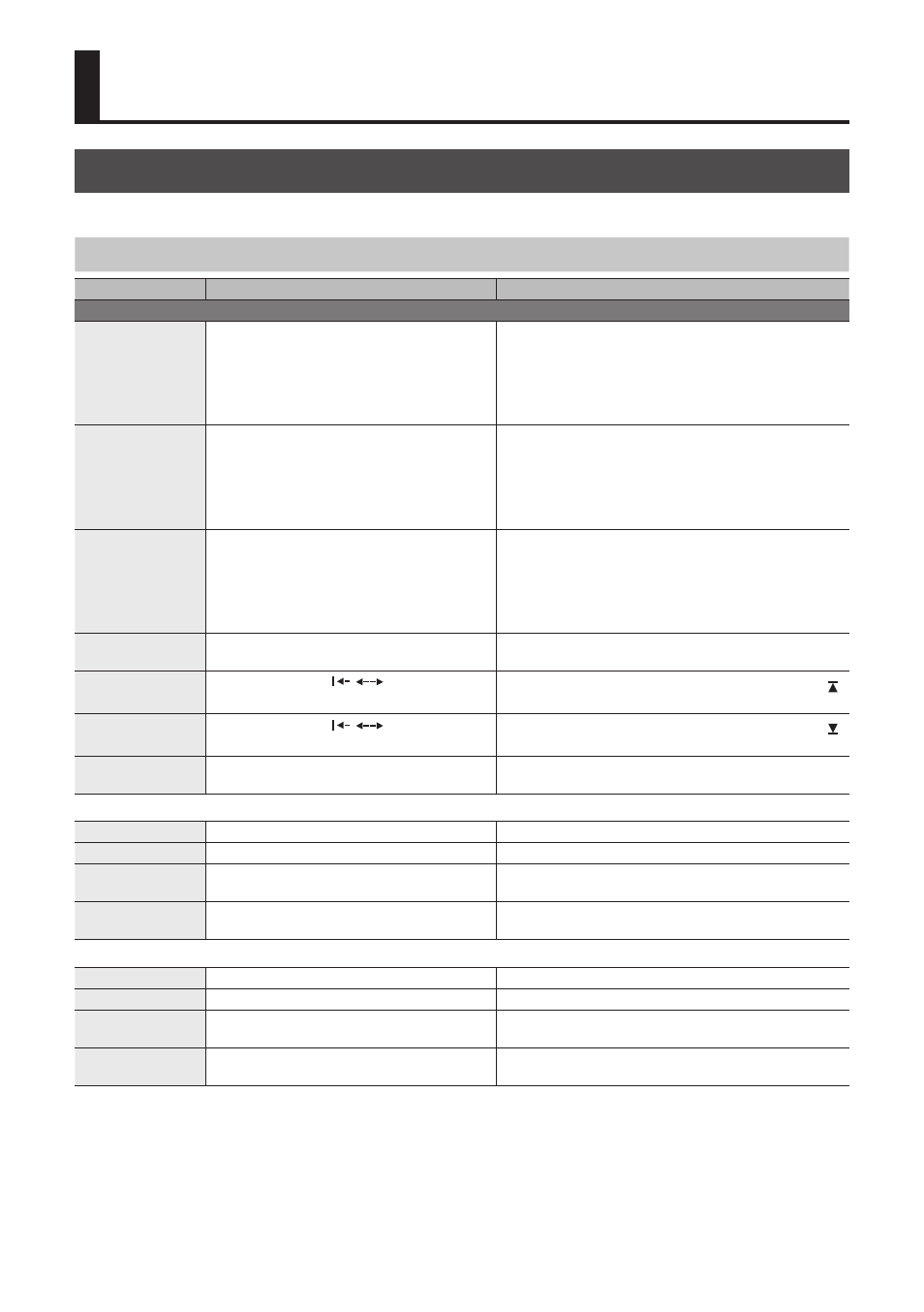
MEMORY Menu
([MEMORY] button
g
[A-1]–[A-4] and [B-1]–[B-4] buttons)
Menu item
Value
Explanation
MEMORY1–MEMORY8
EFFECTS A
NEGATIVE, EMBOSS, COLORIZE, COLORPASS,
POSTERIZE, SILHOUETTE, MONOCOLOR,
FINDEDGE, FLIP, WHT-L.KEY (*1), BLK-L.KEY (*1),
GRN-C.KEY (*1), BLU-C.KEY (*1), PinP 1/4 (*1),
PinP 1/3 (*1), PinP 1/2 (*1), SPLIT-VS (*1),
SPLIT-VC (*1), SPLIT-HS (*1), SPLIT-HC (*1)
Specifies the effect assigned to the EFFECTS A [ON] button.
EFFECTS B
NEGATIVE, EMBOSS, COLORIZE, COLORPASS,
POSTERIZE, SILHOUETTE, MONOCOLOR,
FINDEDGE, FLIP, WHT-L.KEY (*1), BLK-L.KEY (*1),
GRN-C.KEY (*1), BLU-C.KEY (*1), PinP 1/4 (*1),
PinP 1/3 (*1), PinP 1/2 (*1), SPLIT-VS (*1),
SPLIT-VC (*1), SPLIT-HS (*1), SPLIT-HC (*1)
Specifies the effect assigned to the EFFECTS B [ON] button.
WIPE
(*2)
H-DOWN, H-UP, V-RIGHT, V-LEFT, V-IN, V-OUT, H-IN,
H-OUT, R-DOWN, L-DOWN, R-UP, L-UP, BLOCK,
V-GRID, H-GRID, H-DOWN/s, H-UP/s, V-RIGHT/s,
V-LEFT/s, H-IN/s, H-OUT/s, V-IN/s, V-OUT/s,
R-DOWN/s, L-DOWN/s, R-UP/s, L-UP/s, BLOCK/s,
V-GRID/s, H-GRID/s
Specifies the transition pattern assigned to the [WIPE]
button.
* Setting values indicated with “/s” are soft edge transition
patterns.
MIX
(*2)
MIX, FAM, NAM, MOSAIC
Specifies the transition pattern assigned to the [MIX]
button.
TRANSFORMER A
NONE, TRANSFORM,
,
, WHITE, BLACK,
BPM SYNC, WIPE, MIX, CUT, EFFECTS
Specifies the Function assigned to the TRANSFORMER [ ]
button.
TRANSFORMER B
NONE, TRANSFORM,
,
, WHITE, BLACK,
BPM SYNC, WIPE, MIX, CUT, EFFECTS
Specifies the Function assigned to the TRANSFORMER [ ]
button.
TRANSFORM TIME
0.0–4.0sec, BPM x 1/4, BPM x 1/2, BPM x 1,
BPM x 2
Specifies the length of time for applying a video transition.
If PinP compositing is turned on for bus A, use the following items to adjust the inset screen.
PinP A CROPPING H
1–100%
Adjusts the horizontal size of the inset screen.
PinP A CROPPING V
1–100%
Adjusts the vertical size of the inset screen.
PinP A VIEW POS H
-50–50%
Adjusts the horizontal position of the video shown in the
inset screen.
PinP A VIEW POS V
-50–50%
Adjusts the vertical position of the video shown in the
inset screen.
If PinP compositing is turned on for bus B, use the following items to adjust the inset screen.
PinP B CROPPING H
1–100%
Adjusts the horizontal size of the inset screen.
PinP B CROPPING V
1–100%
Adjusts the vertical size of the inset screen.
PinP B VIEW POS H
-50–50%
Adjusts the horizontal position of the video shown in the
inset screen.
PinP B VIEW POS V
-50–50%
Adjusts the vertical position of the video shown in the
inset screen.
(*1) When effects are turned on for either bus A or bus B, no effects can be applied to the other bus.
(*2) For more information about transition patterns, refer to “Transition Effects List” (p. 37).