Appendices – Roland V-1HD+ Compact 4 x HDMI Video Switcher & UVC-01 USB Capture Device Kit User Manual
Page 34
34
Appendices
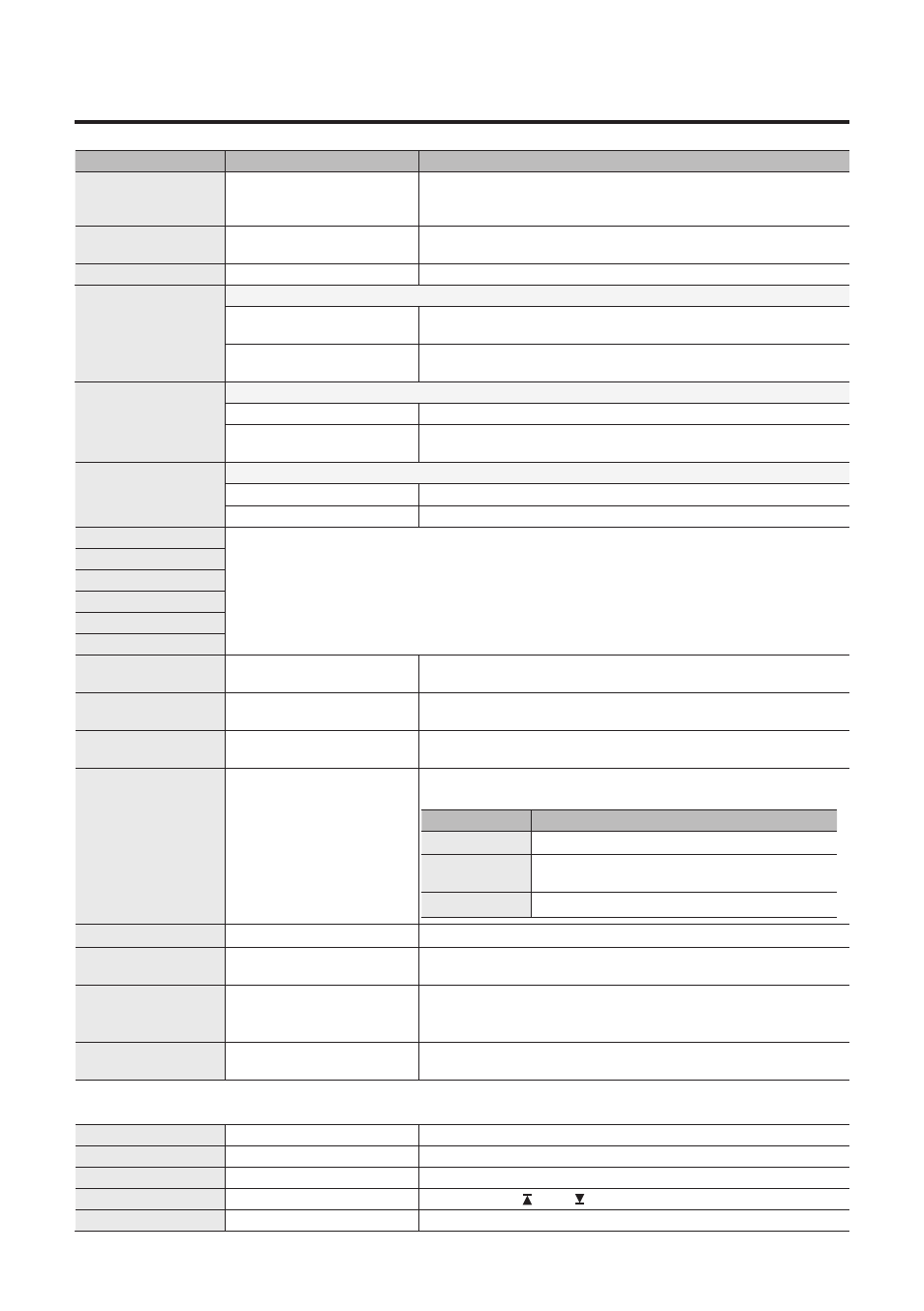
Menu item
Value
(bold text: default value)
Explanation
AUTO SCAN TIME CH1
:
AUTO SCAN TIME CH4
OFF, 1–
5
–120sec
When the Auto Scan function is on, specifies the video display interval.
If this is “OFF,” video switching does not affect.
AUTO SCAN TRANS
TIME
0.0–
1.0
–4.0sec
When the Auto Scan function is on, this sets the length of time for
applying a video transition.
AUTO SCAN SEQUENCE
NORMAL
, RANDOM
Specifies the order in which video signals are shown.
DEINTERLACE MODE
Specifies the method used when converting interlaced input video to progressive video.
WEAVE
Joins the top field and bottom field in a single frame. This is optimal for
video that contains little movement.
BOB
Interpolates the top field and bottom field, and unites them in a single
frame. This is optimal for video that contains much movement.
A/B MODE
Specifies the operation mode for video transitions.
A/B
The video on the bus toward which the A/B fader is flipped is output.
PGM/PST
The video at the PGM (bus A) position is always output, and for PST (the
bus B position), these select the video to be output next.
FREEZE MODE
Specifies the operation mode for freezes.
ALL
Freezes all input video.
SELECT
Freezes only the selected input video.
MIDI Rx SOURCE
For information on remote control via MIDI, download and refer to the “V-1HD Remote Control Guide”
(PDF) from the following Roland website.
https://proav.roland.com/
MIDI OUT
MIDI Tx CHANNEL
MIDI DEVICE ID
MIDI Rx CHANNEL
MIDI Rx TEMPO CLOCK
POWER ON LOAD
1
–8
Selecting a memory number causes the settings at the selected
memory number to be recalled at startup.
PGM LED
RED
, GREEN, YELLOW, BLUE,
PURPLE, L.BLUE, WHITE
Specifies the color used when the output video channel buttons ([A-1]–
[A-4], [B-1]–[B-4]) light up.
PST LED
RED,
GREEN
, YELLOW, BLUE,
PURPLE, L.BLUE, WHITE
Specifies the color used when the buttons for the video channel to
output next ([A-1]–[A-4], [B-1]–[B-4]) light up.
INPUT LED
ON
, OFF
If this is “ON,” the [A-1]–[A-4] and [B-1]–[B-4] buttons light up, flash, and
go dark as shown below.
Button
Input video status
Lit white
Valid video is input.
Flashing white
Video whose format differs from the [FORMAT]
switch setting is input.
Dark
No video is input.
TRANSFORMER LED
ON
, OFF
If this is “ON,” the TRANSFORMER buttons light up in white.
AUDIO LED
MASTER OUT
, MIC, AUDIO IN,
HDMI 1, HDMI 2, HDMI 3, HDMI 4 Specifies the audio signal monitored by the AUDIO indicator.
AUDIO LEVEL METER
OFF, LOWER L, LOWER,
LOWER R
, LEFT, CENTER, RIGHT,
UPPER L, UPPER, UPPER R
Specifies the location of an audio level meter displayed on the preview
monitor.
If this is set to “OFF,” an audio level meter is always hidden.
MEMORY PANEL LOAD
ON,
OFF
Specifies whether the state of the operation panel is updated (ON) or
not updated (OFF) when a memory is recalled.
Use the following items to enable (ON) or disable (OFF) panel lock. Panel lock is a function that disables operation of the
operating panel buttons and knobs.
PANEL LOCK ALL
ON,
OFF
Turns the setting on/off for all buttons and knobs.
A BUS SW
ON,
OFF
[A-1]–[A-4] buttons
B BUS SW
ON,
OFF
[B-1]–[B-4] buttons
TRANSFORMER SW
ON,
OFF
TRANSFORMER [ ] and [ ] buttons
BPM SYNC SW
ON,
OFF
[BPM SYNC] button