KBC Networks H.264 Encoder User Manual
Page 11
Encoder User Manual
Manual-H264_ENC-Rev1207A
Copyright © KBC Networks 2012
Page 11 of 49
www.kbcnetworks.com
The IP addresses do not need to be changed for the units to operate individually
or as a system. If you will be using multiple ENC-H-W* and DEC-A in a system,
please see the advanced operation section of this manual for setup. The ENC-H-
W* and DEC-A operate as a pair and the IP addresses have been set accordingly.
2. Mount the ENC-H-W* at the desired location. The encoder is not weatherproof
and will need to be mounted in a suitable environmental enclosure if used outside
or in a harsh environment. If the ENC-H-W* is part of the Encoder/Decoder Kit
(EDKT-H-W*), the included KBC housing is suitable for outdoor and/or harsh
environments provided the minimum and maximum temperature specifications of
the ENC-H-W* are not exceeded.
3. Connect the analog video cable from the analog video source to the VIDEO-IN
port. If the system requires data transmission (pan/tilt/zoom or other
RS485/422/232 data) connect the wires from the data device the RS485/422/232
Tx+, Tx-, Rx+ & Rx- ports. If the system requires alarm communication, connect
alarm device wires to the Digital Input (DI) ports.
4. Connect the LAN/WAN port of the ENC-H-W* to the wired or wireless network.
The green LED on the front on the ENC-H-W* will illuminate if the encoder is
connected to a valid network/Ethernet device. If connected to a switch or KBC
WESII / MESHII system then a straight through cable is needed for this
connection. If the ENC-H-W* and DEC-A are being tested back to back, a
crossover cable will be needed.
5. Mount the DEC-A at the desired location. The DEC-A is not weatherproof and will
need to be mounted in a suitable environmental enclosure if used outside or in a
harsh environment. Typically the DEC-A will be located in close proximity to the
analog video device it will be connected to such as a monitor, DVR or multiplexer.
6. Connect an analog video cable from the Composite BNC output on the DEC-A to
the input of the analog device it will be connected to. If the system requires data
transmission (pan/tilt/zoom or other RS485/422/232 data) connect the wires
from the control device to the RS485/422/232 Tx+, Tx-, Rx+ & Rx- ports. If the
system requires alarm communication, connect alarm device wires to the Digital
Input (DI) ports.
7. Connect the LAN/WAN port of the DEC-A to a wired or wireless network. The
green and amber LEDs of the LAN port will illuminate if the DEC-A is connected to
a valid network/Ethernet device. If connected to a switch or wireless system then
a straight through cable is needed for this connection. When the ENC-H-W* has
established communication with the DEC-A, The green LED on the ENC-H-W* and
the amber LED on the DEC-A will flash rapidly. Analog video from the analog
video source connected to the ENC-H-W* will be displayed on the device the
Composite output of the DEC-A is connected to.
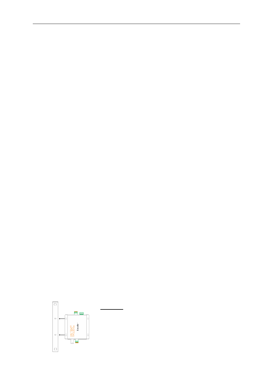
2.3.3 Mounting the Encoder in a KBC LWE-ED enclosure*
See instructions included with enclosure for parts list and dimensions.
1. Attach KBC Encoder to mounting braces using self-thread Philips screws. Ensure
top and bottom holes are positioned at the outside corners and leave connection
loose to be able to screw into the housing. See Figure #1. Mount the Encoder
and brace assembly into the enclosure using four M5 x .9P x 10mm Philips pan
head screws. Tighten all eight screws. Attach the enclosure to a wall or pole (Pole
mounting hardware included).
Figure #1
Encoder and brace
assembly
* LWE-ED Enclosure is included with EDKT-H-W* and WESII-KT-ED system kits.