Rear panel controls, connections and indicators, Mains power inlet and power switch, Rs485 connection – XTA DC1048 User Manual
Page 15: Gpi port, Balanced audio outputs, Balanced audio inputs, Ta x, Dc1048 integrated audio management
Operator’s Manual
DC1048 Integrated Audio Management
Page 15
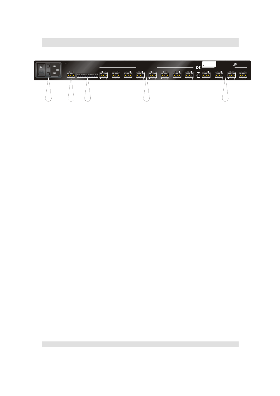
Rear Panel Controls, Connections and Indicators
1: Mains Power Inlet and Power Switch
The mains fuse is also located here, between the switch and the power socket –
only replace with the correct rated fuse.
2: RS485 Connection
To connect a network of DC1048 units, or to include this unit on a network of
other devices, use this connection. The pin-out of this connector is:
Pin 1: Data A (+)
Pin 2: Data B (-)
Pin 3: Shield/Ground
The procedure for setting up a remote network is explained in detail starting on
page 34 of this manual.
3: GPI Port
This port offers a set of input and output connections designed for use with the
WP-1048 touch remote, or for connection to other third party remote control
interfaces, to allow for closed contact preset recall.
4: Balanced Audio Outputs
The analogue outputs are wired as:
Pin 1: Signal Hot (+)
Pin 2: Signal Cold (-)
Pin 3: Shield/Ground
5: Balanced Audio Inputs
The analogue inputs are wired as:
Pin 1: Signal Hot(+)
Pin 2: Signal Cold (-)
Pin 3: Shield/Ground
t
a
x
Serial No:
0000001
D
C
1
0
4
8
90V-240V AC
50 - 60Hz 30W
BALANCED OUTPUTS
WARNING: THIS EQUIPMENT MUST BE EARTHED.
DO NOT EXPOSE TO RAIN OR MOISTURE.
1
2
3 4 5 6 7 8 9 10
GPIO PORT
1-4: OUTPUT
5-8: INPUTS
9: +5V / 10: CHASSIS GND
11 - 12: ISOLATED GND
CAUTION! SHOCK HAZARD.
DO NOT REMOVE COVERS.
RS485
A
B
C
D
1
2
3
4
5
6
7
8
BALANCED INPUTS
MANUFACTURED IN
THE UK BY
ta
x
11 12
INSTALLATION AUDIO MANAGEMENT
DC1048
2
3
4
1
5